
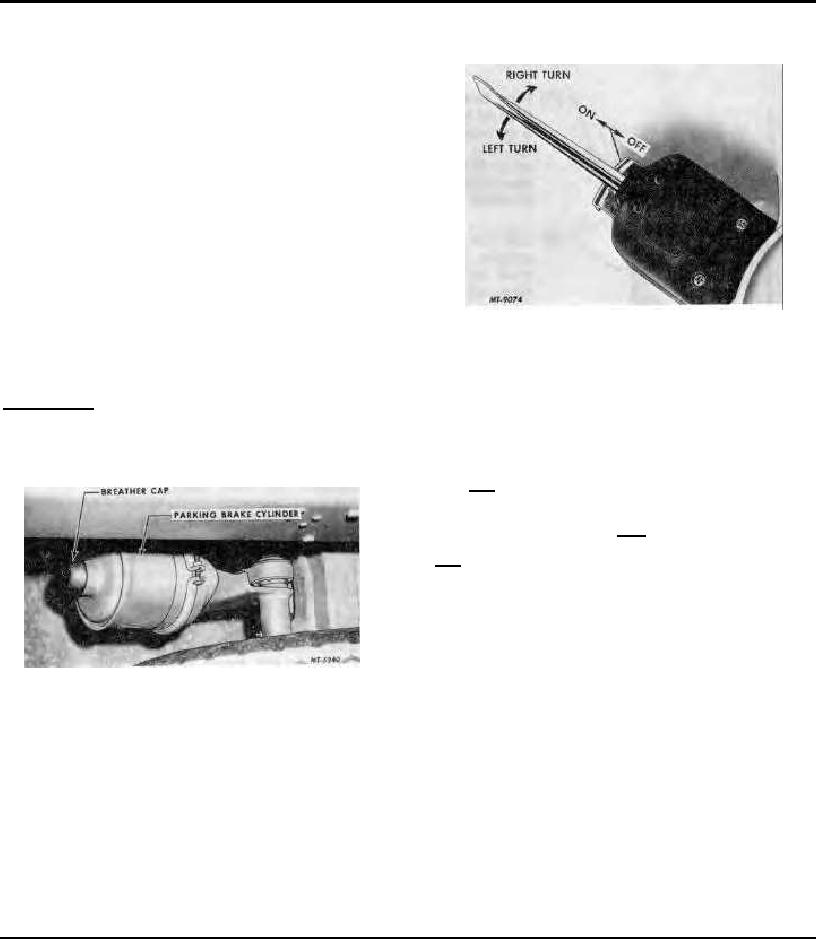
"blink" on and off when the turn indicator is operating.
OPERATION
TRAFFIC HAZARD WARNING LIGHT SWITCH
thereby providing an effective emergency brake.
If the chassis is equipped with a protected reservoir the
parking brake will not automatically apply.
The parking brake cylinder differ from the service brake
cylinders in that the parking brake cylinder apply the
brakes by spring pressure and release them by air
pressure where as the service brake cylinders apply the
brakes with air pressure and release them by spring
pressure.
The parking brake unit requires approximately 60
pounds air pressure before brakes can be released.
Manual Release
In event of air failure on the road or for towing the
vehicle, the spring brake can be released by removing
The traffic hazard warning light switch is required in
breather cap and backing off (counterclockwise) the
several states to flash both front and rear directional
release bolt approximately 1-3/4" until brake shoes are
signals simultaneously, thus warning oncoming traffic of
free from brake drums.
an emergency. The switch is located on the left side of
the steering column.
IMPORTANT: Before releasing spring brakes, be sure
vehicle is properly blocked so that when brakes are
With the turn signal lever in center position, pull switch
released vehicle cannot move.
out to operate signal lights. To turn off, move turn
indicator control to either right or left turn position, then
To Reset Brakes
move back to center position. With switch pulled out,
both turn indicator lights on the instrument panel flash,
indicating operation of both front and rear directional
signal lights. Hazard warning operation is indicated by
simultaneous flashing of both turn signal indicators.
Hazard warning system should be used for emergency
only in compliance with the laws of the state in which the
vehicle is registered.
REAR VIEW MIRROR
The rear view mirror contributes to safe operation of
the vehicle and can be adjusted to the position desired
by the operator.
1. Charge brake system with 60 pounds air
DRIVING THE VEHICLE (Automatic Transmission)
pressure.
Operation of the automatic transmission is controlled
by a selector lever mounted on the cab floor (Console).
2. Turn release bolt clockwise
until
tight.
The position of the lever is clearly shown by a range
(Approximately 50 ft. lbs. torque.)
indicator. When the instrument panel lights are turned
on the quadrant is illuminated.
3. Install breather cap with stainless steel screen
facing down.
TURN INDICATOR CONTROL
The turn indicator control is located on the
steering column below the steering wheel. To signal for
a right turn, push the control away from you. For a left
turn, pull the control toward you. Signal lights on the
front and rear of the truck and on the instrument panel
13

