
AXLE-FRONT
TRUCK SERVICE MANUAL
a. Bend-Over Type Locking Washer
Remove hub cap and gasket. Bend locking
washer to release outer lock nut and inner wheel bearing
adjusting nut. Remove outer nut, locking washer and
inner adjusting nut from steering knuckle spindle.
NOTE:
Always install new locking washer during
reassembly.
b. Dowel and Perforated Ring Type Locking
Washer Remove hub cap and gasket .
Remove outer lock nut, locking washer
perforated lock ring and doweled wheel bearing adjusting
nut from steering knuckle spindle.
3. Remove the outer wheel bearing cone.
4. Remove the wheel and hub assembly.
Steering Knuckle Removal
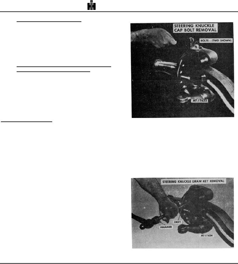
Fig. 4
1. Remove wheel and hub.
5. Drive out the knuckle pin draw key (or keys) from
the small end using a suitable small slender drift,
2. Disconnect tie rod and drag link.
Fig. 5.
NOTE: Straight knuckle pins may be removed
(Older models may employ tapered draw key
from the bottom of the knuckle where adequate
that is threaded on small end and drawn into
clearance is provided; however, on some models
place by a nut. On these models, remove the
such as those with riveted backing plates less
nut and lock washer. Drive the draw key out by
work is involved by tapping the knuckle pin out
use of brass hammer on threaded end.)
the top of knuckle. In either case the adjacent
parts, such as air chambers, hydraulic lines or
fittings, etc, that might cause an obstruction to
the knuckle pin, must be removed first.
3.
Remove the snap rings and expansion plug from
the bottom of the knuckles where employed. If plug
employs no snap ring and is expanded and staked,
remove plug by use of a cape chisel and discard.
4.
Remove the cap screws or bolts, cover plate,
gasket or O-ring from top of knuckle or remove lock ring
retainer and seal, depending on model, Fig. 4.
Fig. 5
14

