
TRUCK SERVICE MANUAL
BRAKES-AIR
CHAPTER IV
MIDLAND ROSS
BRAKE VALVE
Description (Fig. 1)
The foot-operated brake valve is the main air control
device of the air brake system. While some different
models or types may be encountered, all brake valves
are similar in construction and are operated by either a
brake treadle or pedal.
Movement of the treadle or pedal controls the
movement of an inlet and exhaust valve which controls
the air pressure delivered to or exhausted from the brake
chambers.
Full depression of the treadle or pedal results in a full
brake application, partial movement of the treadle or
pedal results in correspondingly less braking force.
At any time, the brakes may be partially released by
the driver permitting a partial return of the treadle or
pedal to release position.
The amount of force being applied to the brakes is
always proportional to pedal pressure applied by the
driver.
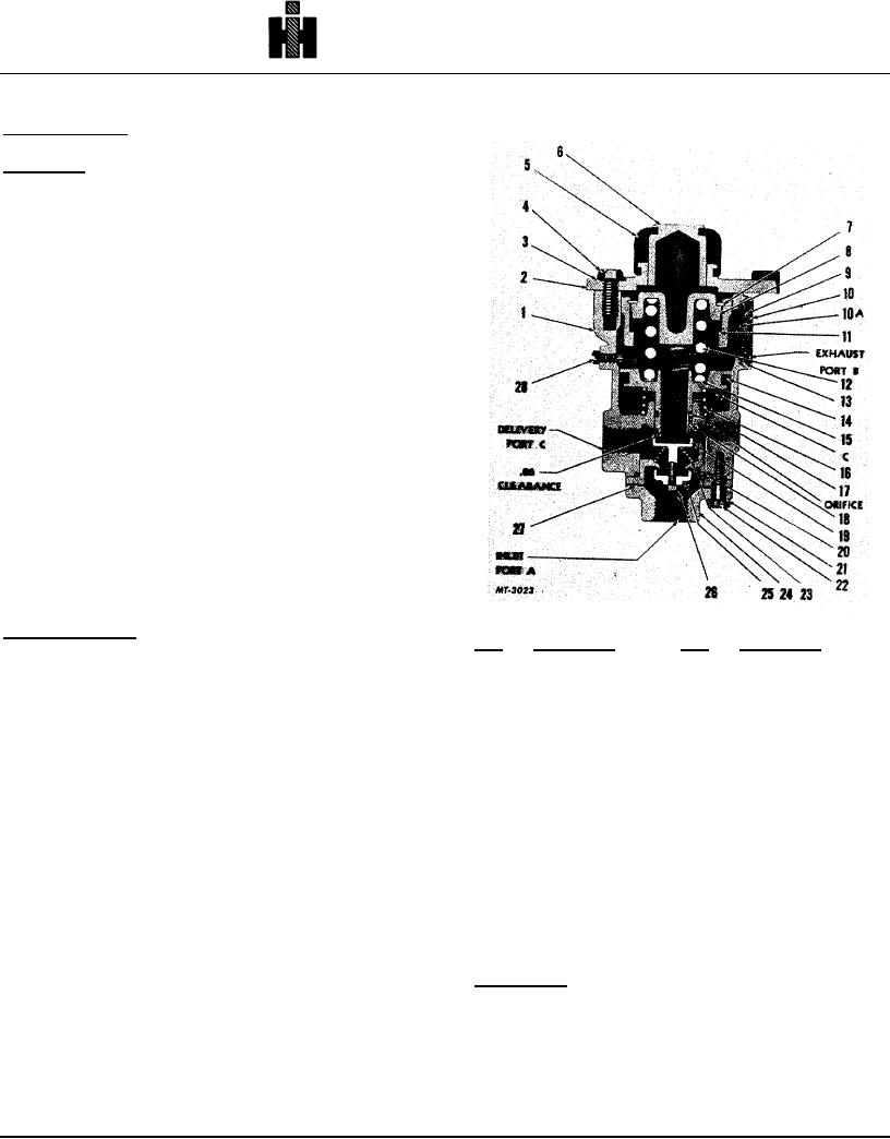
Legend for Fig. 1
Operation (Fig. 1)
Key
Description
Key
Description
As the driver depresses the treadle or pedal,
1.
Body
15.
Washer, shim
pressure is exerted against the plunger which moves the
2.
Plate, mounting
16.
Spring
piston down to close the exhaust valve and open the inlet
3.
Washer, lock
17.
"O"-ring
valve. This permits air pressure at the inlet port (A) to
4.
Screw, cap
18.
Piston
flow past the inlet valve and out the delivery port (C) to
5.
Boot
19.
Valve, exhaust
the brake chambers to apply the brakes.
6.
Plunger
20.
"O"-ring
7.
Ring, snap
21.
Washer, lock
Reservoir air pressure also passes through to a
8.
Guide spring
22.
Screw, cap
small orifice to cavity (C). When this pressure is equal to
9.
Cleaner, air
23.
Spring, valve
the mechanical force applied by the treadle, the piston
10.
Cap
24.
Cap, end
moves up to close the inlet valve cutting off further
10A.
Screen
25.
Valve, inlet
supply of air pressure to the brakes. The exhaust valve
11.
Washer, shim
26.
Nut
remains closed preventing any loss of air pressure. In
12.
Spring
27.
Gasket
this position, the brake valve is in the lap position and
13.
Ring, snap
28.
Screw
instantly responsive to any movement of the treadle to
14.
Seal, vee-block
increase or decrease air pressure being delivered to the
brake chambers.
Disassembly (Fig. 1)
When the driver returns the treadle or pedal to its full
1. Scratch mark end cap, cage, body and mounting
release position, the piston completes its upward
plate to assist in correct positioning for
movement to unseat the exhaust valve. All pressure in
assembly.
the service line, not exhausted through a quick release
2. Remove boot (5).
valve, is released through the center of the piston and
3. Remove three cap screws (4), lock washers (3)
the brake valve exhaust port (B).
and mounting plate (2).
151

