
TRUCK SERVICE MANUAL
ENGINE
free of any erosion scratches or blemishes which are more
Water Passages
than 0.003 inch [0.08 mm] deep in the area 1/16 to 3/32 inch
1. Check all water passages to make sure they are open
[1.59 to 2.38 mm] from edge of water holes. Use ST-1010
and for eroded water holes which may prevent proper seating
Water Hole Counterboring tool to enlarge hole for sleeve. See
of head gasket or grommet retainers,
Service Tool Instructions, Page 343
2. Water holes not eroded more than 1/16 inch [1.59 mm]
1. To install water passage sleeve Part No. 191079:
from edge of hole can be sleeved.
a. Slide sleeve onto stop end of ST-1010-9 Bushing
3. Check for erosion within 1/32 to 3/32 inch [0.79 to 2.38
Driver.
mm] from liner counterbore; if not too deep, block may be
b. A sealant may be used to coat sleeve before
resurfaced. Block must clean up before removing a maximum
installation, if desired.
of 0.010 inch [0.25 mm] material.
c. Align sleeve in top of water passage hole and drive
sleeve in with a hammer until it bottoms. Sleeve will protrude
PARTS REPLACEMENT AND REPAIR
above surface of block.
After a thorough inspection of cylinder block, bushings and
main bearing caps, the decision must be made whether to
2. If block is to be resurfaced, see "Top Surface
install a new or reconditioned block assembly, replace
Refinishing." If not to be resurfaced, file bushing flush with top
bushings or caps and how much can be done to rebuild or
of block, using a wide, flat mill file.
recondition the reusable parts.
Top Surface Refinishing
Camshaft Bushing Replacement
If necessary, a cylinder block may be salvaged by removing a
Bushings may be removed and installed with ST-782 Bushing
maximum of 0.010 inch [0.25 mm] of material from the top
Driver and ST-784 Mandrel or ST-1228 Camshaft Bushing
surface.
Driver Kit. The bushing at No. 7 journal must be installed so it
1. Use either a milling machine or large surface grinder;
is away from rear face of block so oil can drain from hole at
locate block on main bearing pads.
end of camshaft to prevent hydraulic lock.
2. Remove dowels from head mounting surface and
Main Bearing Cap Replacement
make light cuts of 0.001 to 0.003 inch [0.03 to 0.08 mm] deep,
removing only enough material to make block usable.
1. Replacement main bearing caps have 0.015 inch [0.38
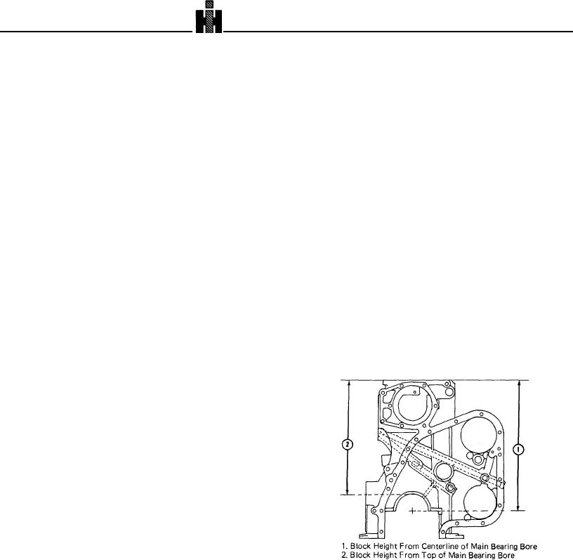
3. Check distance from centerline of main bearing bore
mm] material in bore. Other dimensions are the same as
(1, Fig. 1-2) to top of block. See Table 1-1 (4).
finished main bearing caps. No. 7 replacement cap does not
have cap-to-block dowel holes and must be machined to block
width.
2. Main bearing caps provide 0.0015 to 0.0045 inch [0.04
to 0.11 mm] interference fit in block.
3. If the cap is a rear cap (No. 7):
a. Remove locating dowels from block. Locate cap so
thrust faces of cap and block are flush. Use Prussian Blue on
block surface to locate dowel holes in cap.
b. Remove cap, drill dowel holes. Reinstall cap and
ream dowel holes to the smallest permissible oversize. Install
dowels in block.
4. Install all caps on block and machine bore as
described in Service Tool Instructions, Page 347
Sleeve Eroded Water Holes
The cylinder block surfaces around the water holes must be
Fig. 1-2 (N10181) Cylinder block height check location.
333

