
TRUCK SERVICE MANUAL
ENGINE
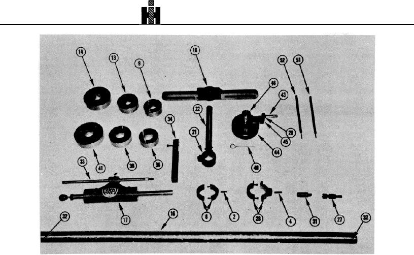
2.
Cutting Tool
17.
Bore Feed Assembly
31.
Drive Adapter
43.
Micrometer i
4.
Cutting Tool
18.
Bore Bar Bridge
32.
Capscrew
44.
Micrometer Base
8.
Cutter Holder
21.
Bearing Bridge
33.
Torsion Bar
45.
Micrometer Bracket
9.
Checking Ring
22.
Bearing Bar
34.
Bracket
46.
Micrometer Shaft
13.
Checking Ring
27.
Swivel Joint
36.
Centering Ring
49.
Cutter Pin
14.
Checking Ring
28.
Cutter Holder
39.
Centering Ring
51.
Allen Wrench
16.
Bore Bar
29.
Capscrew
41.
Centering Ring
52.
Allen Wrench
Fig. 1-16, (ST-1177). Exploded view of ST-1177 Boring Tool
2. Coat outside of sleeve lightly with a suitable sealant
ASSEMBLY TO BLOCK
and drive sleeve into bore with driver until it bottoms (see ST-
1. Remove two undamaged main bearing caps.
1168-36 through 46). A solid sound can be heard when
Preferably one from each end of block or as far apart as
sleeve bottoms.
possible.
3. The sleeve will protrude above the top of block by
2. Insert proper centering rings, with oiler up, in two bores
0.004 inch [0.10 mm] and must be filed even with the top of
and tap top of centering ring with plastic hammer to seat.
block. Remove all burrs with emery cloth.
3. Reinstall main bearing caps and torque to required
4. The salvage sleeve is designed to be 0.005 to 0.010
specifications, following steps in Table 1-1 (18).
inch [0.13 to 0.25 mm] above required counterbore depth.
Note: If centering ring must be installed in journals which
Check depth and cut to specifications listed in Table 1-1 (2).
have had caps replaced by semi-finished caps, limit torque to
ST-1177 Main Bearing Boring Tool
10 ft-lbs [1. kg m].
This tool is designed to perform both the boring and checking
4. Oil centering ring bores and boring bar, install boring
functions.
Before boring operation, allow tool and block
bar
to stabilize to room temperature.
347

