
TRUCK SERVICE MANUAL
ENGINE
lubricating oil or soluble oil and water solution for proper
2. Use a flat mill file to file sleeve flush with top of
finish. Do not ream valve guide beyond worn limit as
cylinder head. Do not damage head surface. Remove
listed in Table 2-1 (3).
burrs from inside diameter of sleeve, clean all cuttings
and filings from water passages.
Replace Crosshead Guides
3. If proper sleeve is not available, heavy wall
1. Remove crosshead guides marked for
copper tubing may be used. Tubing must provide 0.002
replacement using ST-667 or ST-1134 Dowel Puller.
to 0.005 inch [0.05 to 0.13 mm] press fit. Overall length
2. Using ST-633 Crosshead Guide Mandrel, press
should be approximately 1/2 inch [12.70 mm]; inside
new guides into cylinder head. If mandrel is not
diameter must be 7/16 inch [11.11 mm] to allow proper
available, press new guides into head to obtain
water flow.
protrusion as listed in Table 2-1 (6).
Resurface Cylinder Head
3. Oversize crosshead guides may be installed as
If cylinder head has been scratched, etched or is uneven
follows:
at point of contact in gasket sealing area, head may be
a. Drill guide bore in head to original depth with a
milled or surface ground.
29/64 inch [11.51 mm] drill.
1. Use ST-1 133 Valve Seat Extractor, remove all
b Lubricate and ream bore with 15/32 inch [11.
valve seat inserts.
mm] reamer.
2. After resurfacing check head height, use
c. Install oversize guide, Part No. 161527, as per
micrometer or vernier depth gauge. Do not remove
Step 2 above.
more than indicated as worn limit. See Table 2-1 (1).
Replace Valve Seat Insert
3. Rework valve seat insert counterbore, remove
1. If cylinder head has not been resurfaced, use
amount of stock equal to that removed during cylinder
ST-1133 Valve Seat Extractor to remove valve seat
head resurfacing.
inserts that are marked for replacement.
Replace Valve Guides
2. Enlarge counterbore to next oversize. Inserts
1. Drive out guides marked for replacement from
are available in standard oversizes as listed in Table 2-1
underside of cylinder head. Install new valve guide with
(8).
ST-1217 Mandrel or if valve guide bore in cylinder head
has been damaged, install oversize guides as follows:
a. Using ST-1188 Reamer, ream defective valve
guide bore in head to 0.760 to 0.761 inch [19.30 to 19.33
mm]. Ream through, remove all burrs. Corner break
should not exceed 0.015 inch [0.38 mm].
b. Using ST-1217 Mandrel, press oversize valve
guide, Part No. 208362, into cylinder head.
Note: If damaged valve guide bore does not clean up,
use ST-1187 Reamer, Ream 0.765 to 0.766 inch [19.43
to 19.46 mm] and use oversize valve guide, Part No.
208363. Repeat Steps a and b above. It may be
necessary to ream valve spring guide hole to 0.768 to
0.773 inch [19.74 to 19.75 mm] to accommodate
oversize valve guides.
2. If proper valve guide mandrel is not available,
press guide into head. See Table 2-1 (3).
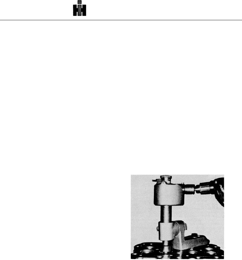
Fig. 2-10 (N 10288) Counterboring for valve seat with
3. Normally valve guide inside diameter does not
ST-257
require reaming. Insert valve stem into guide and check
for freedom of movement.
4. If reaming is necessary: Ream valve guide from
bottom side of cylinder head using ST-646 Reamer. Use
357

