
TRUCK SERVICE MANUAL
FUEL SYSTEM
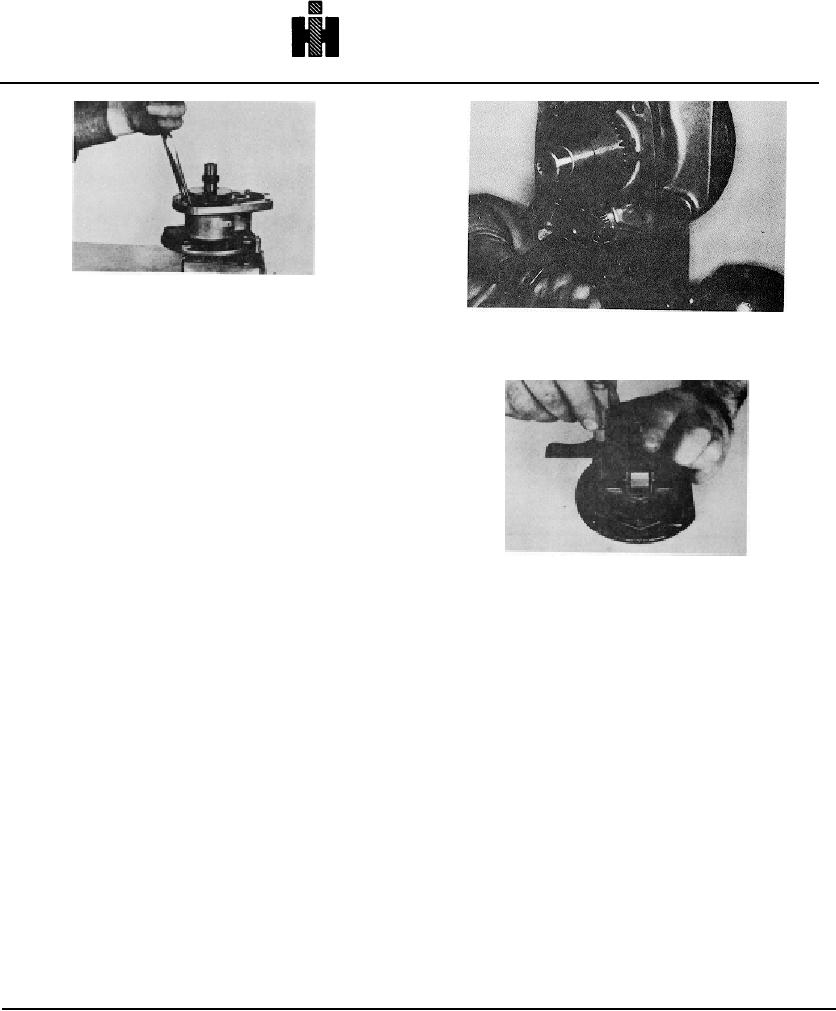
Fig. 5-57, F544. Securing snap ring in groove
4. Line up oil groove in top of tachometer drive bushing
Fig. 5-58, F5305. Installing weight assist plunger in cast
with fuel pump drive shaft. Press bushing, shaft and
weight carrier.
gear
assembly into cover until bushing bottoms.
5. Install spacer on top of bushing with slotted edge
down. Install new oil seal, with spring side down. Spacer
must bottom on bushing.
Caution: Do not overpress spacer.
It can be
flattened eliminating its effectiveness.
6. Cover top of seal with a thin coat of lubricating oil.
Secure tachometer housing to cover.
7. 'Install key, press coupling and front tachometer drive
gear into position on drive shaft. Press slow and straight.
Be certain tachometer gear teeth are aligned.
Fig. 5-67, F546. Measuring assist plunger protrusion
8. Install coupling retainer flatwasher, lockwasher and
capscrew to shaft and tighten in place. Hold coupling or
CHECKING PROTRUSION WITH DEPTH MIKE
main shaft in a copper-jawed vise while tightening.
1. Place one leg of the depth mike base of pedestal
9. Coat governor-carrier bushing with high pressure
across the carrier walls and measure down to the front
lubricant and press welded carrier assembly into front
cover gasket surface (no gasket). Fig. 5-67. Move the
cover with ST-1231. Press cast carrier assembly into
depth mike to the opposite side of the carrier and again
front cover using a driver contacting carrier and shaft
measure to the front cover gasket surface directly across
between weights. Mesh gears to avoid gear tooth
the cover from the previous measurement (do not turn
damage. The bushing must seat against housing.
carrier or cover). Average these two measurements.
Rotate weight assembly, with weights opened out, to be
This procedure is necessary to eliminate any possible
sure it will turn completely in housing.
influence of uneven carrier wall heights.
10. Install shims, when required, spring and governor
2. Position the depth mike across the carrier directly
assist plunger between governor weights and into bore of
over the weight assist plunger. Measure down to the
governor weight carrier shaft. Fig. 5-58.
plunger. Do not depress spring.
Note: Always check and assemble weight assist plunger
3. Subtract "Step 2" from the average determined under
with smallest end of plunger to weights. This will prevent
"Step 1". The result is the weight assist protrusion. If
weights from sticking. Governor assist plunger is used
weight assist protrusion is below specifications, (see Fuel
only on PT (type G) fuel pumps.
Pump Calibration Data) add shims. If the weight assist
11. Use enough shims back of spring to make governor
protrusion is above specifications, remove shims or grind
assist plunger protrude above gasket face of front cover.
the exposed end of the weight plunger (grind only if no
Gauge protrusion with a dial depth gauge having a base
shims are being used).
approximately 4 inches long or use ST-1120 or ST-1241.
Note:
Refer to calibration data for weight assist
protrusion pertinent to pump being rebuilt.
511

