
STEERING
TRUCK SERVICE MANUAL
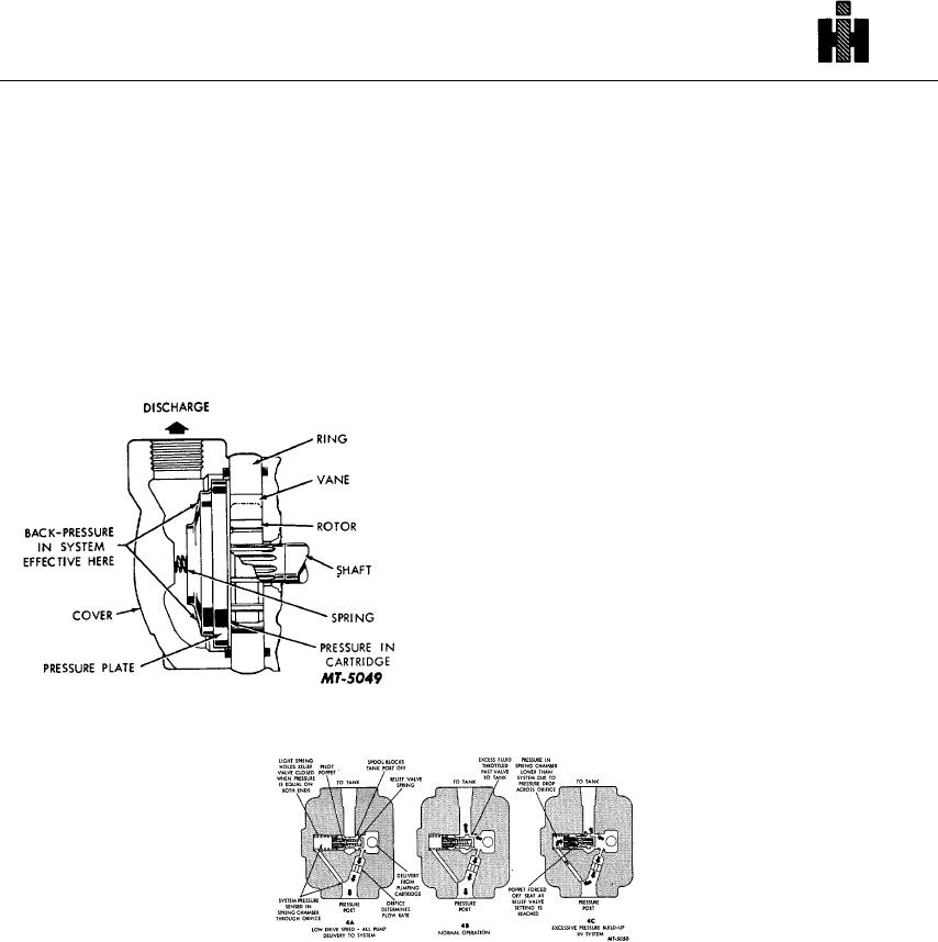
The pump ring is shaped so that the two pumping
Maximum pump delivery and maximum system
chambers are formed diametrically opposed. Thus,
pressure are determined by the integral flow control and
hydraulic forces which would impose side loads on the
relief valve located in the cover.
This feature is
shaft cancel each other out.
illustrated schematically in Fig. 4.
The pressure plate seals the pumping chamber as
An orifice in the cover limits maximum flow. A pilot-
shown in Fig. 3. A light spring holds the plate against
operated type relief shifts to divert excess fluid delivery to
the cartridge until pressure builds up in the system.
tank, thus limiting the system pressure to a prescribed
System pressure is effective against the area at the back
maximum.
of the plate, which is larger than the area exposed to the
Fig. 4A shows the condition when the total pump
pumping cartridge. Thus, an unbalanced force holds the
delivery can be passed through the orifice.
This
plate against the cartridge, sealing the cartridge and
condition usually occurs only at low drive speeds. The
providing the proper running clearance for the rotor and
large spring chamber is connected to the pressure port
vanes.
through an orifice. Pressure in this chamber equalizes
pressure at the other end of the relief valve spool and the
light spring holds the spool closed. Pump delivery is
blocked from the tank port by the spool land.
When pump delivery is more than the flow rate
determined by the orifice plug, a pressure build-up forces
the spool open against the light spring. Excess fluid is
throttled past the spool to the tank port as shown in Fig.
4B.
If pressure in the system builds up to the relief valve
setting, Fig. 4C, the pilot poppet is forced off its seat.
Fluid in the large spring chamber flows through the spool
and out of the tank. This flow causes a pressure
differential on the spool, shifting it against the light
spring. All pump delivery is thus permitted to flow to
tank.
Fig. 3
Fig. 4
DISASSEMBLY
During disassembly, pay particular attention to
removed unless defective. Fig. 5 is an exploded view
identification of the parts, for correct reassembly. Pump
which shows the proper relationship of the parts for
bearings are pressed in the body or on the shaft and
disassembly and reassembly.
should
not
be
626

