
TRUCK SERVICE MANUAL
BODIES AND CABS
LUBRICATION
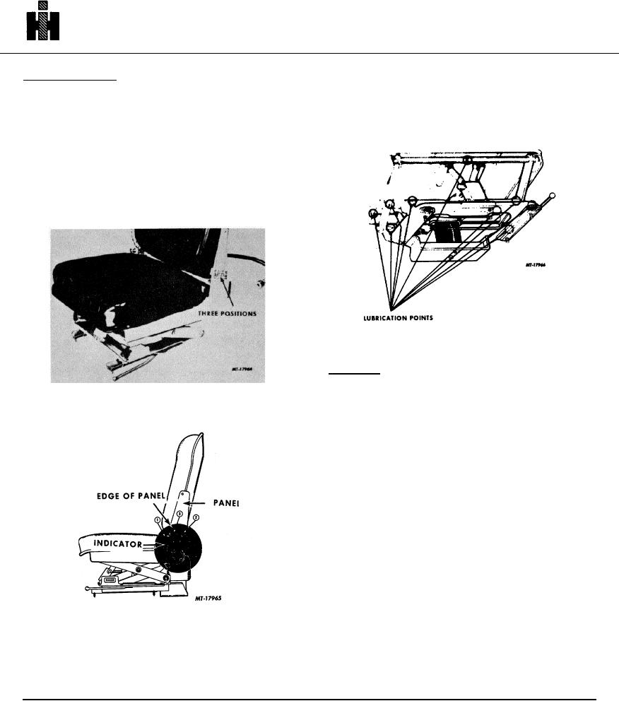
Ride Level Indicator
Lubricate the air suspension seat at locations shown
The indicator located inside the left panel (Fig. 5)
in Fig. 6 using IH 251H EP grease or equivalent NLGI #2
provides positive assurance that the seat is properly
multi-purpose lithium grease.
adjusted for the driver's weight.
1. If there is too much air pressure, the indicator (1) will
be forward of the panel edge.
2. If insufficient air exists, the indicator (2) will remain
behind panel edge.
3. Adjust air pressure until indicator (3) is even with the
panel edge.
Fig . 6
REMOVAL
CAUTION: Release air pressure by pulling
button on control valve out, before performing
Fig . 4
any service.
AIR SUSPENSION SYSTEM
1. Disconnect air supply.
2. Wedge upper seat in top position by using a wood
shim under tube located under front of seat cushion
or by shim under tube located below back of
cushion.
3. Release air spring assembly from seat base
assembly by removing machine screw and lock
washer. This may necessitate removing entire seat
from vehicle.
4. Disengage air reservoir from seat, right and left side
panels by removing capscrews and lock washers.
This permits entire air suspension system to be
removed as a unit as shown in Fig. 7.
Fig. 5
120