
TRUCK SERVICE MANUAL
ELECTRICAL
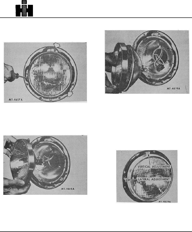
2. Remove the retaining ring attaching screws Fig.
4. Disconnect the connector plug from the sealed
5. NOTE The screw mounting hole: may have
beam unit and remove unit. Do not damage
enlarged openings which permit the retaining
wiring, Fig. 7.
ring to pass over the screw heads after
loosening the screws 4 or 5 turns. Complete
removal of screws is not required.
Fig. 7
ADJUSTMENT
Fig. 5 3
NOTE: Always adjust the headlights
3. Remove the retaining ring and sealed beam unit
with the truck empty and on a level floor.
from the headlight, Fig. 6. In the event the
retaining ring is equipped with the enlarged
The lateral or side adjustment is accomplished by
screw mounting holes rotate the ring clockwise
turning the adjusting screw at side of headlight as shown
enough to permit the ring to pass over the screw
in Fig. 8.
heads.
The vertical or up and down adjustment is
accomplished by turning the adjusting screw at top of
headlight also shown in Fig. 8.
Fig. 6
Fig. 8
277