
TRUCK SERVICE MANUAL
ENGINE
Vehicle Braking Group 20
2. Install special locking plates on two studs
COMPRESSION BRAKE
located in center of each housing. Tighten nuts to 55 to
60 ft-lb. [7.6 to 8.3 kg m] torque in sequence as shown in
Jacobs Brake (Compression)
Fig. 14-9.
3. Bend long tab of each special locking plate down
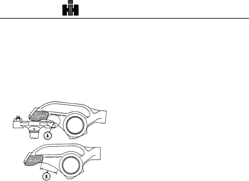
CHECK CROSSHEAD.TO ROCKER LEVER
over housing surface, bend one short tab up against flat
CLEARANCE
of each hex nut.
Barr engine in direction of rotation until valves are closed
Slave Piston Adjustment Procedure
on each cylinder as checked through firing order, hold
lever in contact with Jacobs Brake crosshead and check
Loosen and back off locknut, Insert socket head wrench
interference between crosshead and lever, clearance
and back slave piston adjusting screw out of housing
must be as shown in Fig. 202 (A). If feeler gauge will
until slave piston seats in it's bore.
not pass
Slave piston adjustment must be made with the engine
stopped (warm or cold) and the exhaust valves closed.
Bar the engine in direction of rotation until "A" or "16
V.S." mark on accessory drive pulley lines up with the
timing mark on the gear case cover. With the engine in
this position, the exhaust valves of cylinders 16 are
closed.
Insert a 0.18" feeler gauge between the slave piston and
the crosshead, turn the adjusting screw in until a slight
drag is felt on the feeler gauge. Continue turning engine
in direction of rotation and set slave piston clearance on
cylinders 25 and 34.
To bleed brake units for immediate operation, manually
depress solenoid armature five or six times in
succession with engine running to permit oil to fill
passages in housing.
A. 0.060 Inch [1.524 mm] Clearance
Attach electrical harness to terminal in Engine Brake
B. Grind Area
housing.
Fig. 20-2. (N12045 J). Clearance area between lever and
Mount fuel pump switch and actuating arm using
crosshead
capscrews on fuel pump to secure switch.
through area, remove rocker lever and grind sufficient
Actuating arm may be bent or relocated to contact switch
clearance in area (B), grinding must cover complete area
when throttle lever is in idle position.
in a continuous arc. Grind smooth all sharp edges.
Adjustment
INSTALLATION
Adjust screw in actuating. arm so that audible "click" is
heard when throttle arm moves to an idle fuel position.
1. Install new gaskets and Jacobs Brake units to
rocker housings.
Note: Check PT Fuel Pump throttle shaft to insure that
throttle pedal will move throttle shaft to full fuel position
Note: If studs were removed from rocker housings,
after
installing
the
actuating
arm.
replace and tighten to 65 to 75 ft-lb. [9.0 to 10.4 kg m]
torque in sequence as shown in Fig. 14-9.
436