TM 5-3805-254-20-2
UPPER INSTRUMENT PANEL INDICATOR LAMPS - CONTINUED
ACTION
LOCATION
ITEM
REMARKS
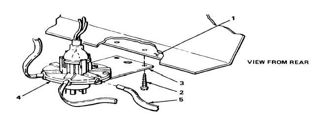
3. Two screws (10) and a.
Using number one cross-tip screw-
REMOVAL
WARNING
Care must be taken when removing lamp that is cracked or gray in color to prevent personal injury.
NOTE
Steps given are typical for removal of two upper instrument panel indicator lamps.
1. Rear of
Socket (2)
Pull out.
indicator (1)
2. Socket (2)
Lamp (3)
Push in, turn counterclockwise, and pull
out.
INSTALLATION
NOTE
Steps given are typical for installation of two upper instrument panel indicator lamps.
3. Socket (2)
Lamp (3)
a. Put in place.
b. Push in, turn clockwise, and release.
4. Rear of gage (1)
Socket (2)
Put in.
TA244245
2-884

