TM 5-3805-264-14&P
CHAPTER 2
OPERATING INSTRUCTIONS
Section I.
DESCRIPTION AND USE OF OPERATOR’S CONTROLS
AND INDICATORS
Paragraph
Number
Paragraph Title
Page
Number
2-1.
Cab-Mounted Controls and Indicators. . . . . . . . . . . . . . . . . . . . . . . . . . . . . . . . . . . . . . . . .
2-1
2-2.
External Controls and Indicators
. . . . . . . . . . . . . . . . . . . . . . . . . . . . . . . . . . . . . . . . . . . . .
2-3
2-1.
CAB-MOUNTED CONTROLS AND INDICATORS.
Key
Control or Indicator
Function
1
Hydraulic Control Lever
Raises and lowers dump body. Squeeze T-handle together and pull lever
back to UP position to raise dump body. Push lever forward to DOWN
position to lower dump body. Place in N (Neutral) detent position to stop
dump body movement.
2
MCS Control Unit
Four toggle switches control LEFT, LEFT CENTER, RIGHT CENTER, and
(M917A1 w/MCS)
RIGHT MCS gates. Move switch(es) forward to OPEN position and rearward
to CLOSE position.
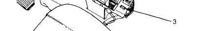
3
MCS Indicator Light
Red light indicates MCS has power.
(M917A1 w/MCS)
2-1