MOTOR TRUCK SERVICE MANUAL
AXLES-REAR
DIFFERENTIAL REMOVAL
Apply enough pressure on the head of the bolt to release the
spring pressure against the nut. Remove the nut and flat
The procedure for removing the differential is the same as
washer by reaching underneath the press. Slowly release the
used for a conventional differential.
IMPORTANT
press and allow the unit to disassemble itself until the spring
PRECAUTION Before disassembling the differential case,
pressure is fully released.
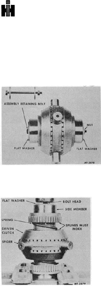
insert a bolt through the center of the NoSPIN unit (axle shaft
openings) with a flat washer on each end against the side
Remove unit from press.
members (Fig. 10).
Remove side members, springs, spring retainers and driven
Thread a nut on the bolt against the flat washer finger tight.
clutch members. The center cam may be removed from the
This will prevent possible injury caused by the unit flying apart
spider by expanding the snap ring with small screw drivers or
due to the spring pressure within itself during disassembly of
wedges.
the differential case.
NOTE : Be careful when removing and reinstalling center cam
snap ring to avoid possible injury.
CLEANING, INSPECTION AND REPAIR
Wash all parts thoroughly with a cleaning solvent. Inspect all
mating surfaces and teeth for possible wear or damage.
Replace all worn or damaged parts before reassembly.
REASSEMBLY
Reassembly is essentially the reverse of disassembly.
Lubricate all parts with SAE30 oil during reassembly. Place
side member upright and install spring on same. Place spring
retainer on spring with flange end toward side member. Install
driven clutch member on spring retainer. Place spider on
driven clutch member, indexing teeth of same. Install other
driven clutch member, spring retainer, spring and side member
Fig. 10 Inserting Assembly Retaining Bolt
on spider.
DISASSEMBLY
Insert a bolt through the center of the NoSPIN unit with a flat
washer against side member. Mount unit in press as shown in
Fig. 11. Compress springs by pressing on head of bolt and
Remove the bolts from the differential case and lift out the
index splines of side members with those of driven clutch
NSPIN unit Mount unit in a small press (Fig. 11).
members NOTE : Keep entire unit aligned in press to prevent
it from kicking out while springs are being compressed.
Compress unit until side member splines are completely
indexed and flush with driven clutch member. Install flat
washer on bolt against side member and thread nut on bolt,
finger tight, so that it has the appearance of Fig. 10 when
removed from the press.
Remove unit from press.
Place unit in differential case and install differential case bolts.
Reassembly from this point is the same as for a conventional
differential.
Fig. 11 Release of Spring Pressure
53

