BREAKS-AIR
TRUCK SERVICE MANUAL
position when the two locking slots in the bearing inserts
and in the rod and cap are both located adjacent to the
same connecting rod bolt. Then install the lock wire
through both capscrew heads and secure. Install the two
capscrews and slotted nuts. Then install cotter pins in
the capscrews.
Turn crankshaft until other journal is downward
and install second connecting rod and piston in same
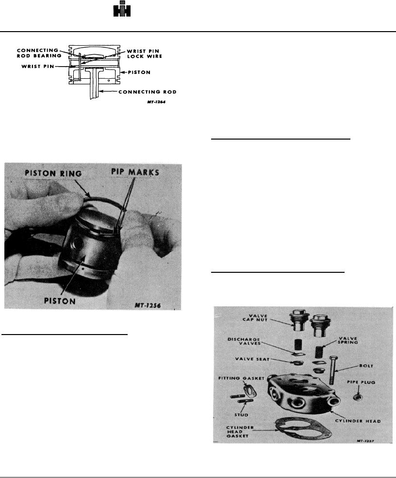
Fig. 10 Installing Wrist Pin Lock Wire
manner.
Install piston rings by hand, Fig. 11. Particular
Assembling and Installing Unloader Pistons
care must be taken when installing piston rings so that
the pip mark on the ring is toward the top of the piston.
Lubricate the unloader piston bores in the cylinder
Stagger the position of the ring gaps.
block and also the unloader piston and unloader piston
grommet with clean engine oil. If new unloader kits are
being installed, the pistons in the kit are prelubricated.
Install unloader piston grommet on unloader piston.
Install unloader pistons and unloader plungers through
the top of the cylinder block taking care to avoid cutting
the unloader piston grommets on the block. Install
unloader spring saddle on unloader plungers. Install
spring seat in top of cylinder block strainer opening and
place unloader spring between spring guide and spring
saddle. Install inlet valve guides if they have been
previously removed.
Assembling and Installing Cylinder Heads
Install discharge valve in the cylinder head.
Install discharge valve spring and discharge valve cap
nut, Fig. 12.
Fig. 11 Installing Piston Rings
Installing Pistons and Connecting Rods
Before installing pistons and connecting rods,
thoroughly lubricate pistons, piston rings, wrist pin
bearings and connecting rod bearings with clean engine
oil.
Turn crankshaft so as to position one crankshaft
journal downward. Remove bearing cap from connecting
rod.
Insert the connecting rod and piston through top of
number one cylinder so that the connecting rod bearing
makes contact with the crankshaft journal. Position and
Fig, 12 Exploded View of Cylinder Head
attach bearing cap to rod. The cap is in the correct
133

