
BREAKS-AIR
TRUCK SERVICE MANUAL
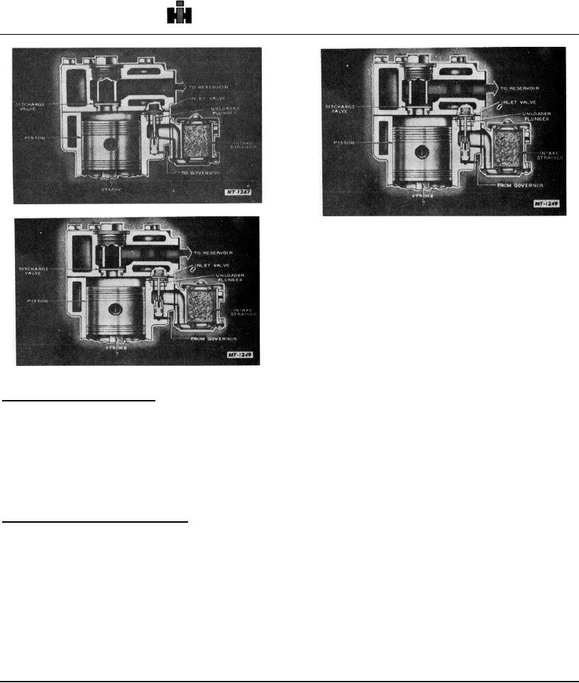
Fig. 3 Intake of Air
Fig. 5 Compressor Unloading Mechanism
REMOVE
1. Drain air brake system.
2. Drain engine cooling system, compressor
cylinder head and compressor cylinder block.
3. Disconnect all air, water and oil lines connected
to compressor.
4. Remove compressor drive belt.
5. Remove compressor mounting bolts and remove
compressor from engine.
6. Use a suitable puller to remove the pulley from
Fig. 4 Compression of Air
the compressor crankshaft after removing the
crankshaft nut.
Not Compressing Air (Unlogded)
DISASSEMB LY
When the air pressure in the reservoir reaches the
maximum setting of the governor (100105 p. s. i. ),
Remove grease or dirt from the exterior of the
compressed air from the reservoir passes through the
compressor by scraping, if necessary, followed by the
governor into the cavity below the unloading pistons in
use of cleaning solvent and a brush.
the compressor cylinder block. This air pressure lifts the
unloading pistons, which, in turn, lift the inlet valves off
TuFlo compressors should have the following
their seats, Fig. 5.
items marked showing proper relationships prior to
disassembly. Center punch marks can be used if
Passage of Air During Noncompression
desired.
With the inlet valves held off their seats the air
during each upstroke of the piston is forced through the
1. Position of cylinder block in relation to
air inlet cavity and to the other cylinder where the piston
is on the down stroke.
2. Position of end covers in relation to the
When the air pressure in the reservoir is reduced to the
minimum setting of the governor (8085 p. s. i. ), the
3. Position of crankshaft in relation to crankcase.
governor releases the air pressure beneath the
unloading pistons. The unloading piston return spring
then forces the pistons down and the inlet valve springs
return the inlet valves to their seats and compression is
resumed.
128