
TRUCK SERVICE MANUAL
BRAKES-AIR
REMOVE
DISASSEMBLY
1. Disconnect air lines from quick release valve.
1. Remove four screws.
2. Remove mounting bolts and valve.
2. Remove spring and spring seat if so equipped.
INSTALL
3. Remove diaphragm.
1. Mount quick release valve with mounting bolts
4. Remove cover O-ring.
and lock washers with its exhaust port pointing
down.
CLEANING AND INSPECTION
2. Connect brake valve to top port and brake
1. Clean all parts in good cleaning solvent.
chamber lines to side ports.
2. Inspect diaphragm, especially the lower part that
3. Make sure exhaust port is not restricted.
contacts the exhaust seat and cover O-ring, for
4. After the new or rebuilt valve is installed, perform
wear or deterioration. Replace if necessary.
tests as outlined under SERVICE CHECKS.
3. Check the cover exhaust seat for pitting or nicks.
This seat should be smooth and sharp. If not,
use a fine piece of emery cloth to dress the seat.
4. Check the spring and spring seat(if valve so
equipped) for wear or corrosion.
5. Clean or replace as necessary.
REASSEMBLY
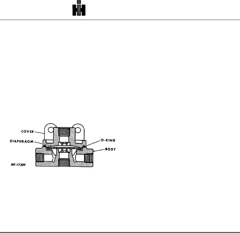
Fig. 2. Sectional View of Quick Release valve
1. If valve is equipped with spring and spring seat,
position spring in body.
2. Position diaphragm over spring seat.
3. Place O-ring in groove.
4. Assemble cover and body.
5. Install four screws and tighten evenly.
154