
BRAKES - AIR
TRUCK SERVICE MANUAL
is angled downward to act as a shield over the plunger
The keyed adjusting pawl assembly is not
seal. This prevents contact between the seal and the
interchangeable with the original adjusting pawl
adjusting spoon when the brake is being adjusted
assembly because of the keyed pawl. However, the
manually. The spring lip serves to protect the plunger
individual spring, gasket and hollow capscrew are
seal when the bolt is in the bottomed position.
interchangeable with original parts.
To further facilitate the initial manual adjustment, the star
NON-PRESSURE
HALF
ASSEMBLY
wheel portion of the adjusting bolt head employs square
teeth.
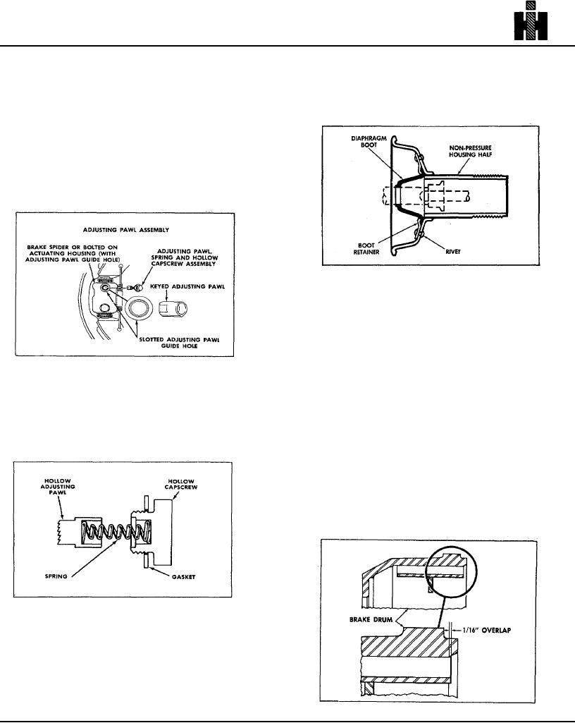
ADJUSTING PAWL ASSEMBLY
The adjusting pawl for the Stopmaster II Wedge brake
employs an integral key which mates with a slot in the
adjusting pawl guide hole of the redesigned brake spider
or actuation housing.
The power unit of the Stopmaster II employs a larger,
and more flexible diaphragm boot seal It also employs a
boot retainer clamp which is riveted to the wall of the
non-pressure half of the housing.
The lip of the
diaphragm boot is positioned beneath the boot retainer
clamp, and Is thus held tightly against the wall of the
nonpressure housing. This provides improved sealing
for the air chamber tube by preventing road
The keyed pawl and slotted guide hole assures correct
contaminates from entering the wedge area and
positioning of the pawl inside the plunger to allow the
contaminating the lubricant. Further, the mechanical
brake to adjust automatically. This design makes it
attachment of the boot retainer clamp prevents possible
necessary for the keyed pawl assembly to be used only
separation of the diaphragm boot from the housing.
with brake spiders and bolted on actuation housings
CHAMFERED BRAKE DRUM
which employ slotted pawl guide holes.
Other design improvements for the Stopmaster II include
a chamfer on the brake drum on the inside outer edge to
facilitate removal when brake service is necessary. The
chamfer allows the brake lining to overlap the drum edge
by approximately 1/16". This, in turn, prevents the
development of scored wear rings on I.D. of the drum,
which could interfere with disassembly.
The keyed adjusting pawl, spring and hollow capscrew
are pre-snapped together as one assembly to facilitate
reassembly of these parts into the spider and bolted on
actuation housings. To achieve this, both the capscrew
and pawl have hollow ends, and the spring has one large
diameter coil at each end which force fits (presnaps) into
the open ends of the pawl and capscrew.
218