
TRUCK SERVICE MANUAL
ENGINE
3. Position "O" ring gasket on housing flange.
ASSEMBLY
4. Install cover and clamping ring; tighten capscrew until
1. Position new copper washer on capscrew.
clamping lugs come together.
2. Insert capscrew in filter case; slide seal spring,
washer, seal and support over capscrew; secure in
Mountings (Fig. 7-3) Vertical Mounting
position with snap ring or circlip in case. Snap ring or
Vertical or up-right filters can be mounted with up to 45
circlip must be in proper position in groove in center bolt.
deg. inclination. The inlet should be positioned at the
3. Coat all plugs and fittings with sealing tape or lead
highest location to minimize drain back of oil when
sealer; install in filter head.
engine is shut-down. None of the vertical mounted filters
4. If removed, insert filter by-pass valve spring (3, Fig.
contain anti-drain back valves on either the inlet or outlet.
7-2) (large end first) in filter head (4), position relief valve
(2) in bore coated side out over spring (3) and secure
Horizontal Mounting
with retainer (1), press retainer in bore flush with head.
Horizontal mounted filters can also be mounted up-right
Note: By-pass valve discs, hard composition type, have
when it is desirable to have both inlet and outlet hose
been replaced by steel disc valves (rubber coated one
attached to bottom end of filter.
side) Part No.
200819.
Hard composition discs
removed, should be replaced with rubber coated steel
discs.
5. Position new seal ring or gasket on filter head; slide
new element with seals in place over capscrew and into
filter case.
6. Position assembly to filter head and secure with
capscrew; tighten to 25 to 35 ft-lbs [4.8 to 5.5 kg m] .
By-Pass Filter
A by-pass filter is often used in conjunction with a full-
flow filter, never use a by-pass filter instead of a full-flow
filter.
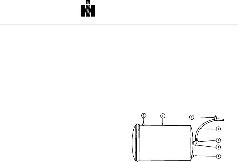
1.
By-Pass Filter
2.
Lubricating Oil Inlet
DISASSEMBLY
3.
Lubricating Oil Outlet
4.
Drain Fitting
1. Remove clamping ring capscrew and lift off cover.
5.
90 Deg. Elbow
6.
No. 10 Hose (Minimum)
2. Unscrew upper support element hold-down assembly
7.
Hose Hump To Be Higher Than Filter Can
and lift out hold-down assembly and element.
Fig. 7-3 (V50709) By-pass filter installation
Flow Characteristics And Specifications
3. Clean housing and hold-down assembly in solvent.
INSPECTION
With a 180 deg. F [82 deg. C] oil temperature and with
1. Inspect hold-down assembly spring/seal, drain plug,
engine at high idle, oil flow through the by-pass filter
connections and filter cover "0" ring.
Replace if
should be a minimum of 1-1/2 to 3 gal. [5.7 to 11.4 lit]
damaged.
per minute maximum (total flow through both filters) to
2. Clean orifice in tee-handle or orifice hole in standpipe;
insure maximum filtration and maintain adequate oil
these are very important and control amount of flow
pressures.
through the by-pass filter.
ASSEMBLY 1. Install new element.
2. Replace upper support element hold-down assembly
in filter and tighten down to stop.
375