
TRUCK SERVICE MANUAL
ENGINE
Hose Size
REPAIR
1. The supply and drain lines should be No. 6 (5/16 inch
[7.9 mm] inside diameter) flexible hose up to 10 ft. [3 m]
Repair damaged tubes by inserting a small O.D. tube
in length. For lines over 10 ft. [3 ri], use No. 8 (13/32
inside damaged tube. Cut and flare ends; then solder
inch [10.3 mm] inside diameter). All fittings in by-pass
securely. Do not damage adjacent tubes with heat while
circuit should be no less than 1/4 inch [6.4 mm] pipe size.
soldering. If more than 5% of tubes are defective,
2. The return line should discharge below oil level in the
discard cooler.
oil pan to prevent foaming.
3. Supply line should be connected to oil circuit between
ASSEMBLY
oil pump and full-flow filter.
1. Lubricate rubber "O" ring and place in groove at
LUBRICATING OIL COOLERS Direct Mounted
bottom of housing. Make sure ring is not twisted and is
DISASSEMBLY
free of cuts or nicks.
1. Remove cooler cover, "O" ring, and brass retainer,
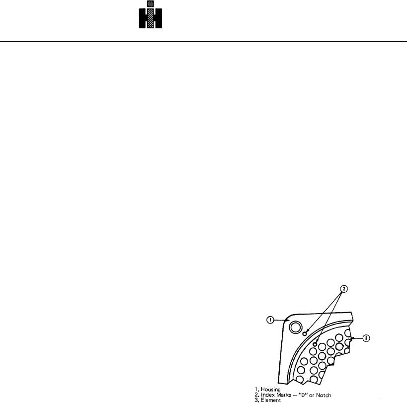
2. Push element (3, Fig. 7-8) into housing (1), aligning
being careful not to scratch or mar sealing surface on
index marks (2) on housing and element.
element.
3. Using proper "O" Ring Mandrel, install "O" ring around
2.
Use mineral spirits or equivalent to clean out
top of element. Place retainer ring over rubber "O" ring.
lubricating oil and contaminants trapped in housing by
4. Install pipe plugs (if removed), on coolers using 3/4
forcing cleaner through the oil ports.
inch pipe plugs with raised bosses torque to 25 to 35 ft-
3. To remove element from housing, insert two 7/32 inch
lbs [3.5 to 4.8 kg ml. Torque others to values in Table 1-
[5.56 mm] rods 8 inches [503.2 mm] long into the outside
1, Cylinder Block Group.
row of tubes opposite each other, rods should not drag
bottom of housing.
Support, Pump Mounted Or Auxiliary Oil Cooler
4. Place a bar on top of housing and bundle face,
DISASSEMBLY
between rods, and rotate element in housing to unseat
lower "O" ring. Lift up gradually on rods to free "0" rings.
1. Remove cooler, cover, support and gaskets from
cooler
INSPECTION
1.
To prevent hardening and drying of foreign
substances, clean immediately, after removing end cover
plates, with approved cleaning solvent that will not harm
non-ferrous metal, blow through core with compressed
air.
2. Inspect core for corrosion or cracks where tubes are
welded to end plates. Inspect connections and liner for
cracks or damage.
3. Inspect cooler assemblies for leakage between oil and
water passages.
a. Clamp cooler assembly in fixture and assemble air
connection.
b. Place unit in water tank and apply 1 to 4 psi [0.07 to
0.28 kg/sq cm] air pressure to water side. Inspect for air
leaks, porosity in casting, etc.
Fig. 7-8 (N10705) Aligning oil cooler index marks
c. Apply line air pressure 35 to 40 psi [2.5 to 2.8 kg/sq
cm] to oil side. Inspect for air leaks.
housing (2, Fig. 7-9) if not previously removed.
2. Remove retainer rings (4) from housing (2).
3. Remove exposed "O" ring (3) under retainer, being
careful not to scratch or mar sealing surface on element.
376