
TRUCK SERVICE MANUAL
FUEL SYSTEM
21. If plunger sticks because of misalignment,
loosen cup retainer, rotate cup one fourth turn,
and retorque. Repeat as necessary.
22. Remove plunger from adapter and lubricate
plunger with test oil. Install spring on plunger
and insert into adapter.
23. Check plunger leakage on ST990 or ST570 as
described c the following pages.
24. Check cup spray pattern on ST668 as described
on the following pages.
25. Another method of checking open cup spray
holes is follows:
a. Remove plunger and spring.
Fig. 6-1-40, F60200. Size location on Injector adapter
b. Fill barrel and cup full of fuel oil.
c. Insert plunger with ST1089, less spring, into
inject( forcing fuel out spray holes. Fig. 6138.
Caution: At anytime fuel is forced
from cup spray holes be sure to keep
hands or body out of pray stream to
prevent injury.
d.
Remove plunger and install spring.
26.
Lubricate and install new "Viton" "O" rings into
proper grooves in adapter.
Note: Viton "O" rings are identified by a
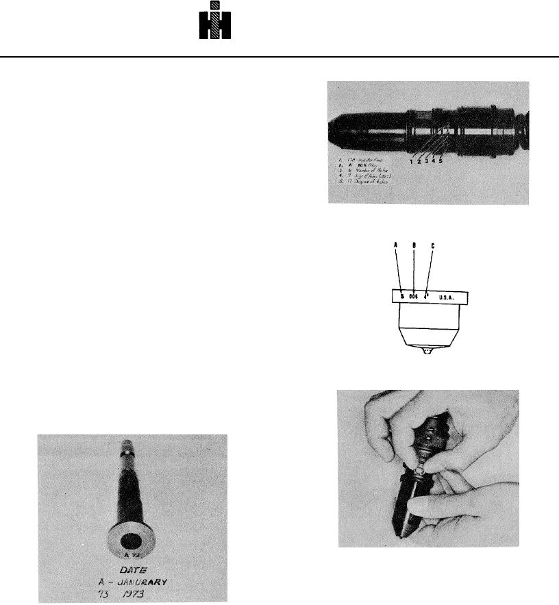
A HOLES
B SIZE
C ANGLE
green band.
Fig. 6-1-41, F60201. Size marking on Injector cup
27.
Install new fuel inlet screen and retainer. Fig.
6142.
28.
After assembly, store in clean place until ready
for leakage test.
Fig. 6-1-42, F60202. Fuel inlet screen and retainer
Fig. 6-1-39, F60199. Marking location on plunger
464