
TRUCK SERVICE MANUAL
Table 6-1-4: Injector Spring Data
Approximate
Wire
Load Required to Compress Springs to Length
Part
Free Length
No.
Dia.
Length
New Min.
New Max.
Worn Limit
No.
Inches [mm]
Coils
Inches [mm]
Inch [mm]
Lb. [kg]
Lb. [kg]
Lb. [kg]
166009
1.95 [49.7]
8
0.187 [4.75]
1.663 [42.2]
143,25 [65]
158.75 [72]
138 [63]
6. Check socket for wear or cracking
Injector Cup
Caution: Handle injector plunger with care to
1. Inspect injector spray holes and tip with magnifying
glass. Compare with new cup shown in Fig, 6-1-17.
prevent damage which could render it useless.
Discard cup if any of following conditions exist.
a. Abrasive wear. This wear can begin internally,
Injector Spring
therefore, inspect both interior and exterior. Fig. 6-
1-18.
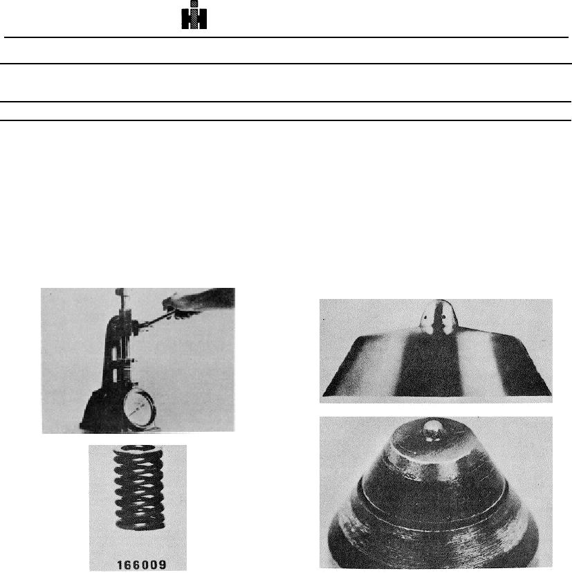
1. Check spring for excessive wear or mutilation.
b. Corrosion damage and effect of excessive heat:
This condition usually results from high acid or
2. Test spring tension on spring tester, Fig. 6-1-15,
sulphur content in fuel or overload operating
that is capable of very accurate measurements of
conditions. Fig. 6-1-19.
spring lengths and applied load by means of
c. Enlarged or distorted spray holes. Caused by
standards and dial indicator gauge. Table 6-1-4
cleaning with drills or other instruments.
Fig. 6-1-17, F60105. New injector cup tip
Fig. 6-1-15, F60163. Testing injector spring
Fig. 6-1-18, F60223. Cup tip damaged by wire brushing
Fig. 6-1-16, Injector spring
2. Inspect cup for plunger seat pattern. If plunger seat
3. If injector springs compress to dimensions shown, at
covers 40 percent continuous area around cup cone
less than load indicated under "worn limits," springs
or plunger bore, it is possible cup may be reused, but
must be discarded.
it must pass the ST-990 cup-to-plunger leak test.
Seat location is not important. Fig. 6-1-20.
Caution: Never alter size of injector cup spray
holes.
460