
TRUCK SERVICE MANUAL
The PT fuel system is used exclusively on Cummins
Diesels. The identifying letters, "PT," are an abbreviation
for "pressure time."
Injector Description
The PT Injector is a simple mechanical unit which
receives fuel from the fuel pump under pressure and
meters, injects and atomizes it through fine injector cup
spray holes into the combustion chamber.
The general description "PT Injectors" is used only to
indicate that the injector is used with the PT fuel system
and not with the former Cummins Disc fuel system.
Cylindrical PT (type D) Injectors
The PT (type D) Injector is a refinement of the PT (type B
and C) cylindrical injectors used in Cummins engines
with internal fuel drillings. The PT (type D) top stop
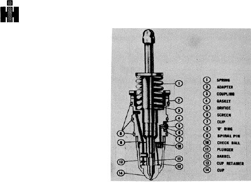
injector is shown in Fig. 6-1-5.
By parts design changes, the PT (type D) provides more
parts interchangeability and those areas subject to wear
Fig. 6-1-5, FWC27. Cylindrical PT (D) injector cross-
are localized in smaller parts for easier servicing.
section
Former injectors have a body with the moving part or
Top Stop Parts
plunger running the full length, the PT (type D) has a
The top stop injector parts are the same as the standard
short barrel and plunger to provide the same function.
PT (type D) except the adapter (2, Fig. 6-1-5) is longer
The shorter barrel plunger bore made possible use of
to accommodate the stop. The plunger coupling top is
materials with greater wear resistance and results in
smaller, allowing it to pass through the stop. The injector
smaller replacement assembly.
The barrel/plunger
spring washer (15), adjustable stop screw (16) and stop
assembly is made up of a coupling (3, Fig. 6-1-5),
screw locknut (17) are parts required only for top stop
plunger (11) and barrel (12); the coupling and plunger
injectors.
are swaged assembly.
Disassembly
The "Top-Stop" injector functions like the standard PT
The disassembly, cleaning, inspection, repair and
(type D) injector except the upward travel of the injector
assembly procedures described on the following pages
plunger is limited by an adjustable stop. The stop is set
are those operations that may be performed in a clean,
before the injector is installed in the engine. Fig. 6-1-5.
well equipped shop.
Operations other than those
Injector Parts-PT (type D)
described must be performed in a qualified Cummins
Adapter
Rebuild Station.
In Fig. 6-1-5, the adapter (2) houses the plunger return
PT (type D) Injectors
spring (1), adjustable orifice (5), orifice gasket (4), fuel
screen (6) and screen retainer (7) and carries the "O"
1. Lift out injector plunger and spring. Remove spring
ring seals (8) on the outside which seal against the head
from coupler and test as described on the following
to form fuel inlet and drain passages. Fuel enters
pages
through orifice (5) and flows to barrel (12), pass check
2. Store plunger by standing on coupling end.
ball (10) to the cup-to-barrel passage up to the metering
orifice where it is metered into the cup (14). Fuel not
Note: Injector barrels and plungers are class fit, do
used circulates past the metering orifice, around the
not interchange.
plunger and out the drain passage while the plunger is
seated in the cup. The cup, adapter and barrel are held
3. Remove "O" rings from injector adapter and discard.
in assembled position by the cup retainer (13).
Metering Orifice of PT (type D) Injector
4. Remove button-style screen retainer ring, and
The metering orifice near the cup end of the barrel is of
remove screen. Check screen and discard if
fixed size and must not be altered In any way, barrels
damaged.
differ for engine model In relation to the size of the
metering orifice as governed by engine fuel requirements
458