TRUCK SERVICE MANUAL
INSTRUMENTS
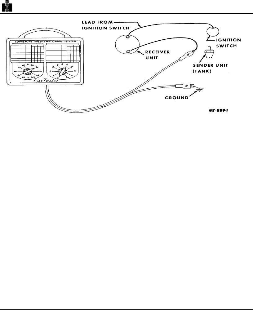
Fig. 24. Checking Fuel Level Gauge System Components
As the tank unit resistance varies between the
gauge should read slightly above "full. " If tests are
extremes of 0 and 90 ohms due to changes in the fuel
satisfactory, indication is that receiver unit and wiring
level, current flow divides proportionately between the
from tank unit to receiver is functioning properly and
two possible paths from point B to ground. The resultant
that tank unit is faulty or is insufficiently grounded to
magnetic fields around the coils control the position of
tank.
the magnet and pointer through the range of scale
readings from empty to full.
5. Disconnect Fastestor and reconnect wire at tank
unit.
The sender and ignition terminals are connected by
a calibrating resistor, Fig. 23. The odd terminal is the
6. If receiver unit does not respond properly to above
ground terminal.
tests, disconnect tank sender unit to receiver wire
from receiver unit terminal, Fig. 25.
The sender terminal is the first terminal clockwise
from the ground terminal when viewed from the back
7. Connect Fastestor lead "A" to receiver unit at sender
terminal and lead "B" to ground.
side of gauge. NOTE: The ground terminal provides a
ground between the gauge and its housing or cover. The
8. Turn ignition switch to "on."
housing is grounded to the chassis through the mounting
studs. When the key switch is turned off, the pointer will
9. Set Fastestor left-hand control knob to "90" and
not necessarily return to the empty position. This is
right-hand control knob to "0. " Gauge should read
inherent in the instrument and does not indicate a faulty
slightly below "empty. " Turn ignition switch "off."
part.
NOTE: A standard test light may be used to check
To determine faulty component, proceed as follows:
wire continuity. Replace any units or wiring found
defective.
1. Disconnect wire at tank sender unit, Fig. 24.
Oil Temperature Gauge:
2. Connect SE-2081 Fastestor lead "A" to end of
sender unit wire and Fastestor lead "B" to ground.
The electrical oil temperature gauge consists of two
basic components--the dash gauge and a thermister
3. Turn ignition switch to "on."
sending unit. The gauge indicates the oil temperature,
while the sender controls the gauge reading. The two
4. Set Fastestor left-hand control knob to "90" and
units are connected electrically as shown in Fig. 8.
right-hand control knob to "0. " Fuel
576B

