
TRUCK SERVICE MANUAL
TRANSMISSION
ASSEMBLY
Para 7-18
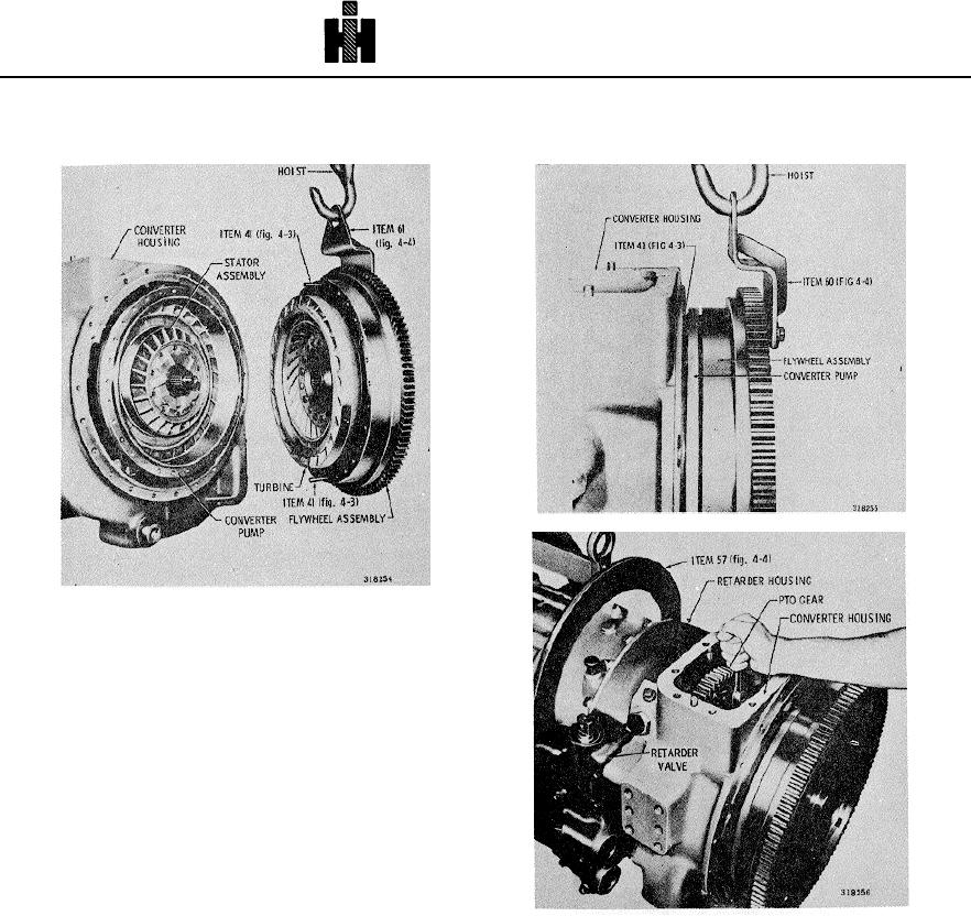
Fig. 7-60 Installing flywheel on the converter pump
Fig. 7-58 Installing flywheel and turbine
gear side down. Install one 3/8-24 x 2-inch guide screw
41 (fig. 4-3) into one of the flywheel mounting holes (fig.
7-58).
(3) Carefully lift the flywheel to a vertical position
and attach a lifting bracket 60 (fig. 4-4) opposite the
guide screw. Retain the bracket with 1/2-20 bolts.
(4) Attach a hoist to the lifting bracket. Aline the
flywheel assembly with the transmission (fig. 7-58).
b. Installation
(1) Push flywheel assembly straight onto the
Fig. 7-60 Installing flywheel retaining bolts
transmission, alining guide screw 41 (fig. 4-3) through
one bolt hole in the converter pump. Engage turbine
(3) Release the hoist and remove the lifting bracket.
splines with the forward clutch shaft splines (fig. 7-59).
(4) Install the remaining 29 bolts and flat washers
(2) Using the access hole at the top of the converter
(fig. 7-60). Prior to installing the last bolt and washer,
housing install one 3/8-24 x 1 1/4-inch bolt and one 3/8
remove guide screw 41 (fig. 4-3).
flat washer through the converter housing into the
flywheel assembly (fig. 7-60).
(5) Tighten the bolts to 41 to 49pound feet (56 to 66
Nm) torque.
788