
TRUCK SERVICE MANUAL
TRANSMISSION
ASSEMBLY
Para 7-20/7-21
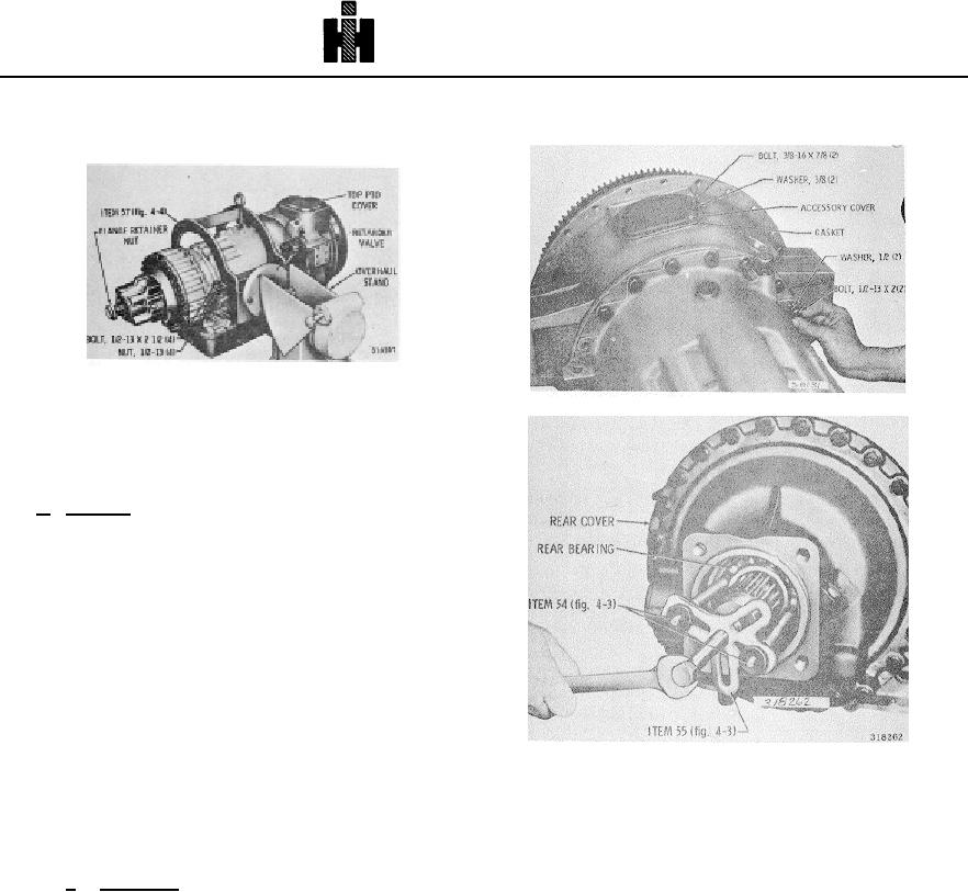
Fig. 7-63
Removing transmission from
overhaul stand
Fig. 7-64 Installing converter housing retainer bolt
7-20.
REPLACING OUTPUT SHAFT
SEAL, BEARING, SPEEDOMETER
DRIVE GEAR (in vehicle)
a. Removal
(1) Remove the vehicle drive shaft from the
transmission output flange. Remove the speedometer
driven gear from the transmission rear cover. Remove
the output flange.
(2) Remove the dust shield, oil seal and rear
bearing snapring (refer to para 6-22a).
(3) Using puller assembly 53 (fig. 4-3), remove the
rear bearing. The legs of the puller assembly are
designed to be locked between the inner and outer ball
races of the bearing assembly. The bearing is pulled by
Fig. 7-65 Removing rear bearing
tightening the puller screw against the rear of the output
(4) Install the speedometer driven gear into the
shaft.
transmission rear cover. Connect the speedometer drive
cable.
(4) Remove the spacer and speedometer drive
gear.
(5) Install the vehicle drive shaft (refer to vehicle
service manual).
b.
Installation
(1) Install the speedometer drive gear, and spacer
7-21.
CHECKING SHIFT POINTS
and bearing. Use installer 59 (fig. 4-3) and driver handle
28 to seat the bearing.
Refer to paragraph 3-11 for procedures covering
checking and adjusting shift point speeds.
(2) Install the bearing snapring, oil seal and dust
shield (refer to para 6-22b).
(3) Install the rear output flange and tighten the nut
to 750 to 1000 pound feet (1017 to 1357 Nm) torque.
790