TM 5-3805-254-20-2
LEFT INSTRUMENT PANEL OPTICAL RIBBON - CONTINUED
ACTION
LOCATION
ITEM
REMARKS
3. Two screws (10) and a.
Using number one cross-tip screw-
INSTALLATION
NOTE
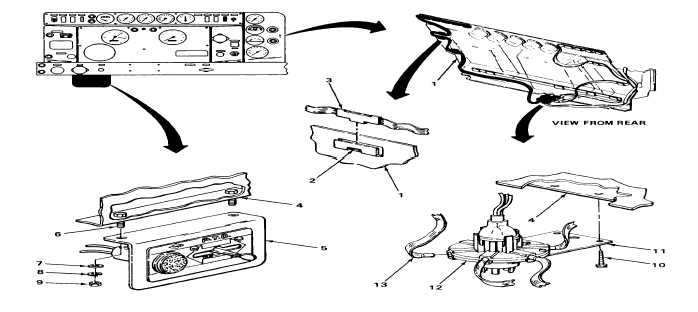
Step 5 is typical for installation of three identification tabs into three bezels.
When installing optical ribbon be sure to start at end farthest away from optical light assembly.
5. Rear of instrument
Bezel (2) and iden-
a. Put in place.
panel (1)
tification tab (3)
b. Push identification tab into bezel.
c. Repeat step b until all identification tabs
are installed in bezels.
6. Optical light Optical ribbon (5) Push in.
assembly (4)
7. Lower center instru-
Two screws (7) and
a. Put bracket in place.
ment panel (6)
bracket (8)
b. Screw in and tighten using number one
cross-tip screwdriver.
TA244251
2-870