
TM 5-3805-264-13&P
OPERATOR MAINTENANCE
DESCRIPTION AND USE OF OPERATOR'S CONTROLS AND INDICATORS
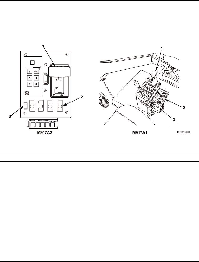
Table 1. Console.
Figure 1. Console.
Key
Control/Indicator
Function
1
Hydraulic Control
Raises and lowers dump body. Squeeze T-handle together and pull lever
Lever
back to UP position to raise dump body. Push lever forward to DOWN
position to lower dump body. Place in N (Neutral) detent position to stop
dump body movement. Lever will not operate to raise dump body if main light
switch is in blackout mode.
2
Material Control
Four toggle switches control LEFT, LEFT CENTER, RIGHT CENTER, and
System (MCS)
RIGHT MCS gates. Move switch(es) forward to OPEN position and rearward
Control Unit
to CLOSE position.
(M917A1 with MCS
and M917A2
with MCS)
3
MCS Indicator Light
Red light indicates MCS has power.
(M917A1 with MCS
and M917A2
with MCS)
03/15/2011Rel(1.10)root(ctrlindwp)wpno(O1000126413)