
TRUCK SERVICE MANUAL
TRANSMISSION
ASSEMBLY
(8)
Install the snapring to retain the
center support (selected in b(7), above). Be sure the
snapring gap is at the top of the transmission housing.
(9) Remove compressor 8 (Fig. 4-2) and
sleeve 7.
c. Second Clutch Clearance
(1) Invert the transmission housing, rear cover
side up.
(2) Remove the six bolts and washers that
temporarily retained the rear cover to the transmission
housing. Remove the rear cover and gasket. (Refer to
figure 7-9.)
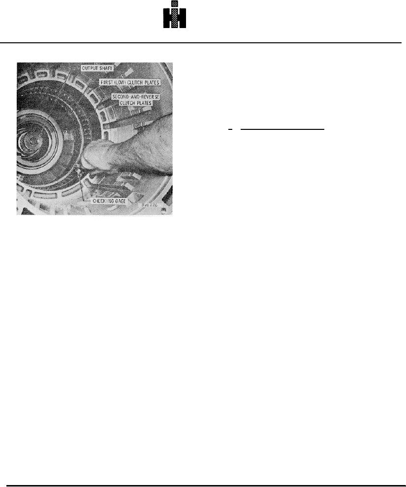
(3) Remove the thirteen low clutch plates from
the adapter housing. (Refer to figure 7-21.) Since these
plates are preset for the low clutch running clearance,
Fig. 7-11. Checking first clutch clearance
they should be maintained in a package form so they
cannot be intermixed with other plates.
tapped hole in the support is aligned with the anchor bolt
hole in the bottom of the housing.
(4) Remove the adapter housing and gasket
from the transmission housing. (Refer to figure 7-28.)
(5) Remove lifting bracket 5 (Fig. 4-2) from
the center support, Install the special 3/8-16 x 2 1/4-inch
(5) Remove the thirteen first clutch plates
anchor bolt into the support through the anchor bolt hole
from the transmission housing. These plates are now
in the bottom of the housing (Fig. 7-5). Tighten the bolt
preset for proper clearance and should be maintained as
finger tight.
a package for final installation.
(6) Place compressor sleeve 7 (Fig. 4-2) on
(6) Using gage 44 (Fig. 4-3), check the
the hub of the center support. Place compressor 8 (Fig.
second-clutch plate clearance (Fig. 7-7).
It is
4-2) across the transmission housing Retain the
recommended the gage be placed between the
compressor bar with two bolts (Fig. 7-6)
transmission housing and the first steel plate. The
prescribed running clearance is 0.095 to 0.145 inch (2.41
(7) Compress the center support with a force
to 3.68 mm). Any dimension within .095 to 0. 145 inch is
of 5 pound feet (6. 78 Nm) torque. Use gage 9 (Fig. 4-
satisfactory. However, the closer the clearance is to
2) to determine the width of the snapring opening while
0.095 inch, the longer the interval between clutch plate
the support is loaded (Fig. 7-6). The lugs of the gage are
replacements will be. Clearance must not be less than
color coded to match the snapring colors. Select one of
0.095 inch. Replace worn plates with new plates to
the snaprings listed below. Select the thickest snapring
establish the desired clearance. Recheck the clearance
that can be put into the groove.
as described above.
Snapring color code
Snapring thickness
NOTE
Leave the second clutch and the center
Blue
0.148-0.150 in.
(3.76-3.81 mm)
support in the transmission housing until
Yellow
0.152-0.154 in.
(3.86-3.91 mm)
the housing is again positioned front end
Green
0.155-0.157 in.
(3.94-3.99 mm)
upward. Begin assembly of Model HT
Red
0.158-0.160 in.
(4.01-4.06 mm)
750CRD at paragraph 7-6.
776

