
BODIES AND CABS
MOTOR TRUCK SERVICE MANUAL
CAB MOUNTING
The cab has a four- point mounting. It is secured to
the frame at each front corner by brackets and rubber
bushing. The rear of the cab is secured in the center at
two places to a crossmember with brackets, rubber
bushings and rubber insulators. Fig. 41 shows details of
the cab front and rear mountings.
CAB REMOVAL
To remove the cab assembly from the chassis,
proceed as follows:
1. Disconnect:
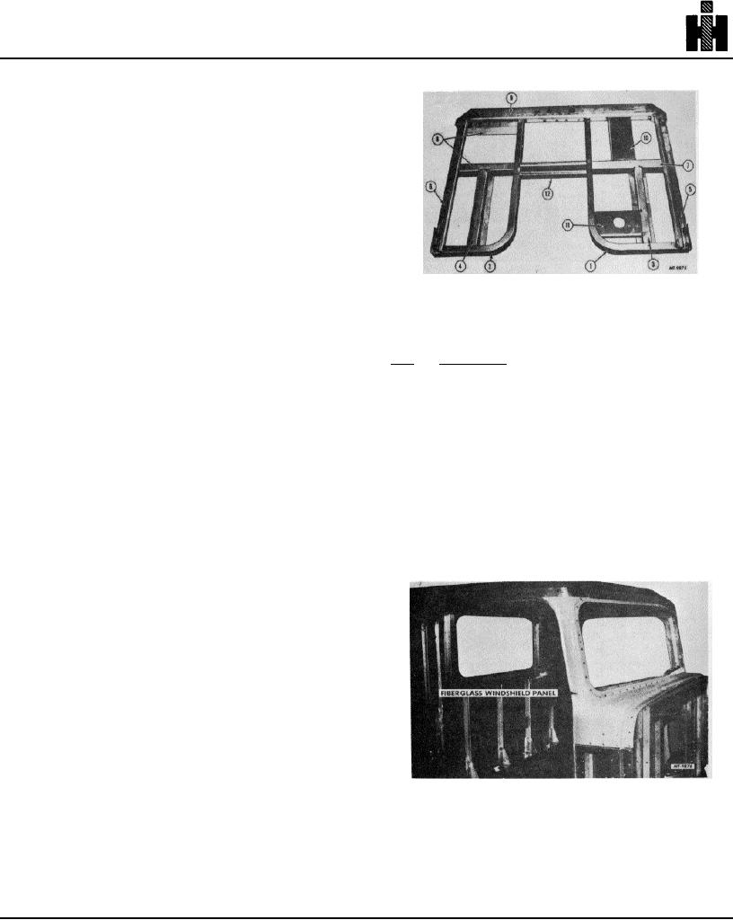
Fig. 43 Cab Floor Substructure
a. Frame-to-cab ground wire.
b. Air lines at brake valve.
Legend for Fig. 43
c. Clutch linkage.
Key
Description
f. Luberfiner hose.
g. Heater hose.
1
CHANNEL, Underbody Inner, Left
h. Speedometer drive cable.
2
CHANNEL, Underbody Inner, Right
i. Tachometer drive cable.
3
SUPPORT, Floor Panel Front, Left
j. Exhaust system.
4
SUPPORT, Floor Panel Front, Right
k. Throttle linkage.
5
SILL, Underbody Side, Left
m. Steering shaft at gear.
6
SILL, Underbody Side, Right
7
SUPPORT, Floor Panel, Left
2. Remove:
8
SUPPORT, Floor Panel, Right
a. Gear shift lever from transmission.
9
SILL, Underbody Rear
b. Cab mounting bolts.
10
SUPPORT, Driver's Seat
11
SUPPORT, Brake Valve
3. Carefully lift cab from chassis.
NOTE: Be
12
CROSSMEMBER, Center
certain all items are disconnected.
CAB FLOOR SUBSTRUCTURE
Fig. 42 shows the various parts of the cab structure
and the legend provides alloy and material thickness
data which will be helpful in the event weld repair is
necessary.
There are sections of the cab understructure that,
once damaged, must be replaced as a complete
assembly. The cab floor substructure, Fig. 43, should be
completely replaced should major damage occur. In
some cases where the sections are only slightly bent, the
parts can be bent back into position or straightened.
Where parts are torn, then complete replacement should
be made.
Do not heat to straighten any section of the cab
Fig. 44
understructure. To do so may destroy the strength of the
members, resulting in early failure. If these areas cannot
CAB STRUCTURE
be satisfactorily cold straightened, then replacement is
required.
Figs. 44, 45 and 46 show various cab panels
and sections and the construction details of
them.
98