TRUCK SERVICE MANUAL
BRAKES-AIR
The anchor pins are designed to withstand 190 all the
braking force of slowing or stopping the vehicle.
The anchors should be inspected for signs of wear. In
most cases rust will be the factor in servicing brake
anchors. Clean all dirt and rust from anchors and coat
them with a very light coat of "Lubriplate 110' or
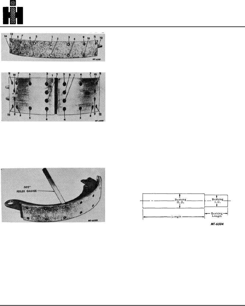
Fig. 14 Sequence in Securing Brake Lining to Shoe
equivalent.
CAMSHAFT, BUSHINGS AND FOLLOWERS
The camshaft is actuated by the movement of the slack
adjuster. The rotating movement of the cam forces the
shoe followers away from the cam, thus forcing the
shoes into contact with the drum.
Removal procedure for camshaft assembly is covered in
the Brake Disassembly procedure. When removing the
camshaft from the backing plate or spider, note the
position of spacing washers to assure correct
Fig. 15 Sequence in Securing Brake Block Lining to
reinstallation, Do not remove camshaft bushings from
Shoe
spider and/or mounting bracket unless replacement is
necessary.
When riveting linings, use a roll set to up-set the rivets.
A star set may split the tubular end of rivet and prevent a
NOTE: Do not interchange right and lefthand camshafts.
tight fit. After the lining is installed, check tightness of
lining to shoe, with a 002" feeler gauge. Gauge should
If camshaft bushings or needle bearings must be
not penetrate past rivets or bolts, Fig. 16.
replaced, a suitable tool (remover) can be made locally
as shown in Fig. 17.
Apply Lubriplate 110 or equivalent to outside diameter of
bushings to assist in pushing them into position
Fig. 16 Checking Tightness of Lining
Fig. 17 Recommended Type of Camshaft Bushing
Removing Tool
After installing the new lining on the shoes, the lining
should be ground in a true radius to fit the drum
BRAKE CHAMBERS
diameter. A brake shoe grinder is provided on brake
reline (SE-1272) which is designed to dress the lining in
Brake chambers (Fig. 18) transform the energy of
a true radius and fit the drum diameter. This grinder
compressed air into mechanical force and motion to
swings the shoe in an arc across the surface of an
apply the brakes. One chamber is used at each wheel to
abrasive wheel.
operate the brakes.
ANCHOR PINS
Air pressure entering the brake chamber, Fig. 18,
behind the diaphragm forces the diaphragm and push
The anchor pins provide a point where the shoes can be
rod outward, rotating the slack adjuster, brake camshaft
secured to the backing plate or spider and also permit
and cam applying the brakes. The higher the air
positioning the shoe in respect to the drum.
pressure admitted to the chamber, the greater the force
190

