
TRUCK SERVICE MANUAL
BRAKES-AIR
of the slack adjuster with suitable cleaning solvent.
2. Cut off heads of rivets (7)-which attach cover plates
(6) to the body. Drive rivets out and remove the cover
plates.
3. Remove the Welch plug (3) from the end of the worm
shaft bore.
4. Position an adapter into the worm shaft bore and
using a hydraulic press, force the shaft out of the body
and worm, freeing the lock sleeve (11) and spring (12).
5. The worm (4) and gear (5) can now be removed from
the body (1).
6. Remove the lubricating fitting or plug if equipped.
7. Remove guide pin (9) from body if necessary.
Cleaning and Inspection
Wash all of the parts in cleaning solvent and dry
thoroughly. Inspect parts carefully. Replace components
when their condition is not satisfactory.
Inspect the bushing in the lever arm. If it is worn, out-of-
round, it must be replaced. To replace the bushing, press
out the old bushing and press the new one into place.
Ream the bushing so that the clevis pin fits the opening.
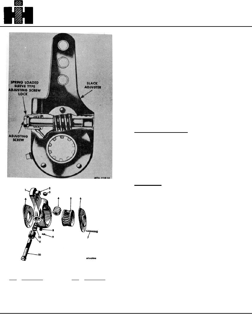
Fig. 20 Sectional View of Slack Adjuster
Reassemble
1. Reinstall new guide pin in body if removed from body.
2. Place the worm (4) and gear (5) in position in the
body.
3. Place the lock sleeve over the worm shaft with the
socket end of the sleeve at the hex end of the shaft.
4. Place the lock spring in the recess formed by the
sleeve and shaft, Fig. 20.
5. Insert the small end of the worm shaft through the
hole in the body and the worm.
6. Press the worm shaft into the worm and body, making
certain the groove in the lock sleeve is aligned properly
Fig. 21 Exploded View of Slack Adjuster
with the guide pin in the body. Press the shaft in until the
Legend for Fig. 21
distance from the small end of the shaft (Welch plug
Key
Description
Key
Description
1
Body slack
7
Rivets
end) to the outside edge of body is approximately 5/8" on
adjuster
8
Plug or fitting
front brakes and 9/16" on rear brakes.
2
Bushing
9
Pin, guide
3
Plug, Welch
10
Shaft, worm
4
Worm
11
Sleeve, lock
5
Gear
12
Spring
6
Plate, cover
193