
MOTOR TRUCK SERVICE MANUAL
BRAKES -AIR
BRAKE ADJUSTMENT
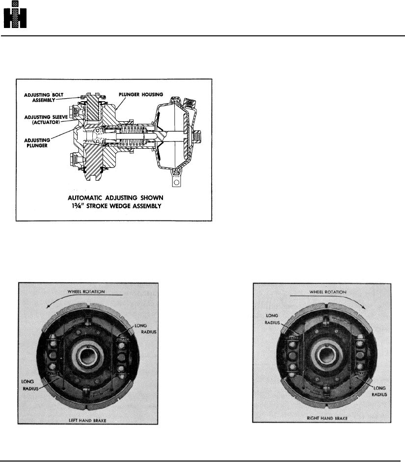
On the automatically adjusted plunger, the adjusting
bolt is threaded into an adjusting sleeve which in
turn is free-fitted inside the plunger proper. The
plunger guide screw is replaced by a hollow cap
screw, a spring, and an adjusting pawl which also
serves as the plunger guide. The end of the
adjusting pawl has saw-tooth type teeth which
engage corresponding helical teeth on the out-
side of the adjusting sleeve.
As the brake is actuated; the plunger, sleeve, and
bolt move outward and the sloping face of the teeth
on the adjusting sleeve lifts the adjusting pawl
(against the spring). When the brake is released,
all the parts return to their starting points. As the
lining wears, the plunger stroke and resulting pawl
lift gradually increases until the pawl climbs over
and drops into the next tooth space. This time,
when the brake is released and the plunger is
pushed back in its bore, the upright face of the pawl
teeth causes the adjusting sleeve to rotate and advance the adjusting bolt. This reduces the lining clearance and the cycle
starts over again. The automatic adjuster operates only in forward vehicle direction.
PLUNGER AND SHOE POSITION
STOPMASTER
BRAKES
(Bolted on Spider
Mounted Integral
Plunger Housing)
On double-actuated brakes, the anchor (solid) plungers should be positioned at the trailing end of each shoe (where they
will absorb the brake torque during forward wheel rotation). This will position the adjustable plungers at the leading end of
the shoes. Also note that the shoe web is unsymetrical. The long-radius end should be engaged with the adjustable
plungers.
199