
BRAKES-PARKING MOTOR TRUCK SERVICE MANUAL
DESCRIPTION
The spring actuated tandem-type parking brake
consists of a tandem-type cylinder connected through the
air brake slack adjuster and brake camshaft to the wheel
brake shoes, Fig. 1.
Fig. 1 Typical Installation of Spring Actuated Parking
Brake.
The cylinder assembly is divided into two sections.
One section is a conventional air brake chamber. The
second section is the spring brake section. This section
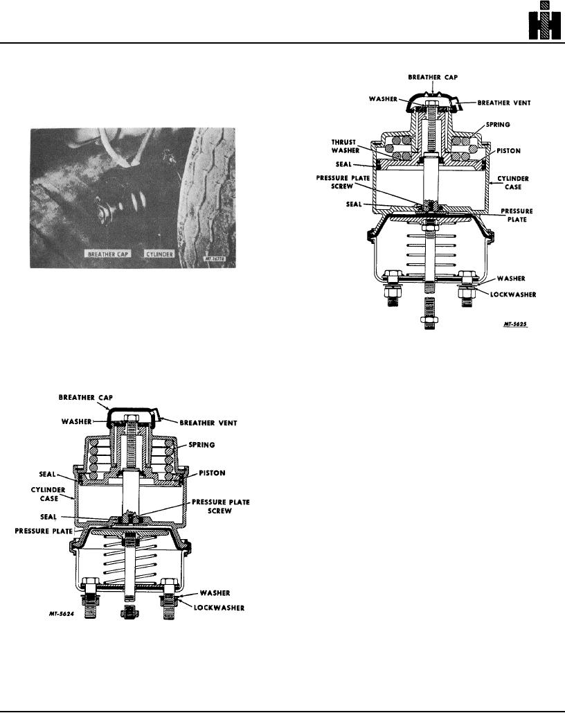
Fig. 3 Type 30 Chamber.
contains a powerful spring which is compressed by air
pressure, Figs. 2 and 3.
loaded cylinders. Upon reduction of air pressure in the
cylinders, the springs apply the rear brakes through
linkages connected to the rear slack adjusters.
To release the parking brake, the driver operates the
control valve to apply air pressure to the parking brake
spring loaded cylinders, thereby, compressing the
springs and releasing the rear wheel brakes.
Upon loss of air pressure or reduction of air pressure in
the vehicles air system, the parking brakes will
automatically apply, thereby, providing an emergency
brake.
In the event of a failure in the service brake system,
the spring parking brakes can be applied.
The parking brake cylinders differ from the service brake
cylinders in, that the parking brake cylinders apply the
brakes by spring pressure and release them by air
pressure. The service brake cylinders apply the brake
with air pressure and release them by spring pressure.
The parking brake unit requires approximately 60 to
65 psi air pressure to be released. At approximately 70
to 80 psi, the springs are fully compressed.
To release the spring brakes (manual
Fig. 2 Type 20 and 24 Chambers.
OPERATION
To apply the spring parking brake, the driver
operates a control valve which exhausts the air pressure
from the spring
229