
MOTOR TRUCK SERVICE MANUAL BRAKES-PARKING
emery cloth (abrasive side against press and tool) to
serve as a nonslip pad between the press ram and tool,
Fig. 14. Depress assembly as shown in Fig. 14.
Use punch, loosen safety washer (counterclockwise for
removing). Remove safety washer and guide washer,
Fig. 15. The safety washer retains the head, spring and
piston assembly. Relax press gradually, Fig. 16. This is
the correct way the head, spring or piston can be
disassembled.
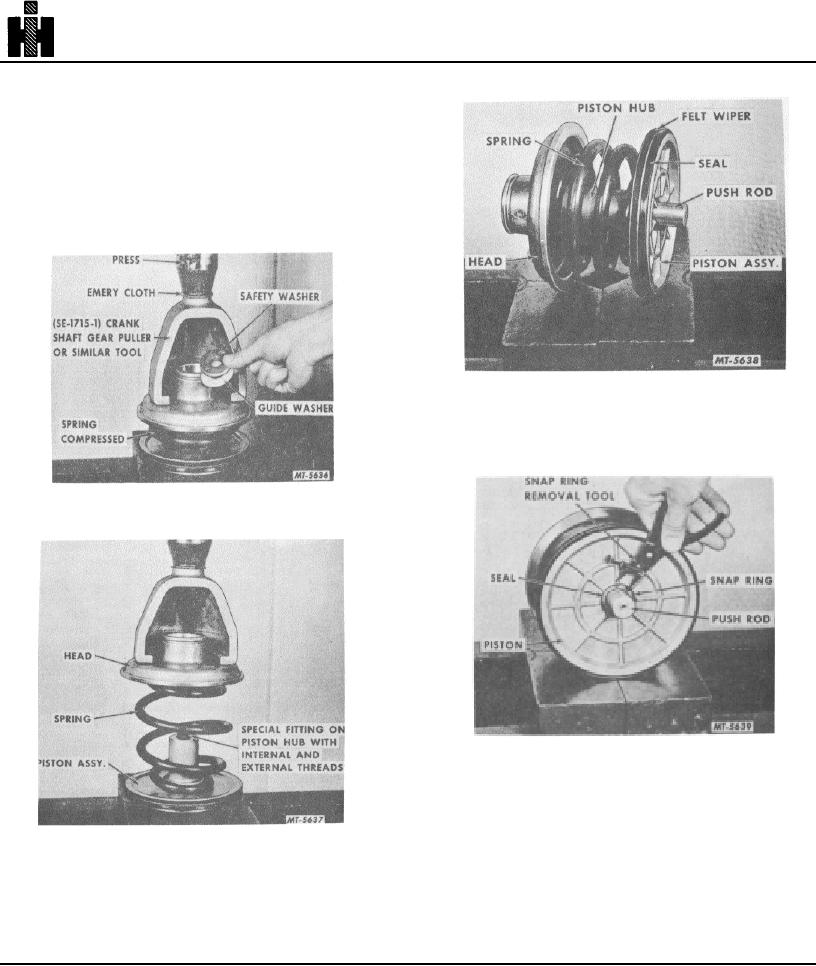
Fig. 17 Piston, Spring and Head Assembly.
Examine push rod for stratches and replace if
damaged.
Fig. 15 Removing Safety Washer and Guide Washer.
Fig. 18 Push Rod Seal Removal.
Remove snap ring from piston and replace push rod
seal if damaged, Fig. 18. Reinstall snap ring, Inspect
push rod seal in bottom of brake chamber housing. If
damaged or worn, replace with new seal assembly. A
Fig. 16 Head, Spring and Piston Assembly with Press
groove is machined directly into the housing for retaining
Relaxed.
the seal.
Clean inside of chamber and all components with a
CLEANING, INSPECTION AND REPAIR
clean solvent before reassembly.
Examine and clean piston felt wiper and seal.
Replace either or both if damaged or worn, Fig. 17.
234