
MOTOR TRUCK SERVICE MANUAL
COOLING SYSTEM
GENERAL
drive bushing (2) out of body flange. An alternate
method is the use of a cape chisel to collapse the
bushing.
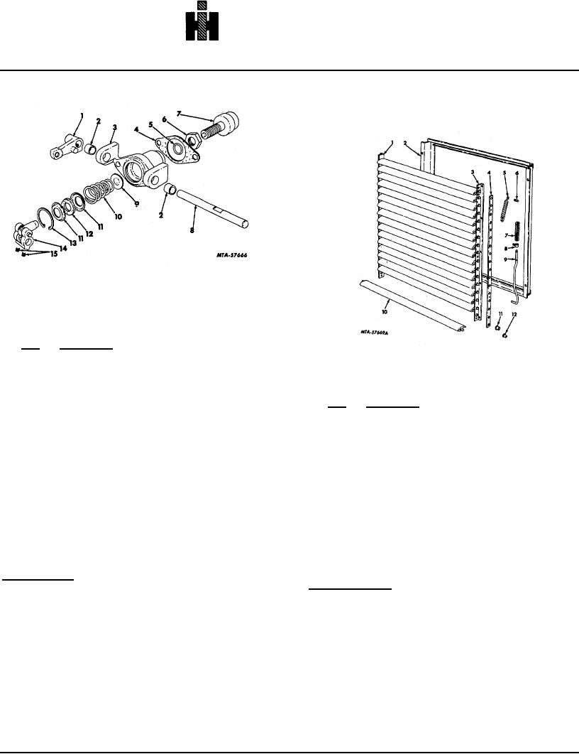
Fig. 2 Radiator Control Assembly (Exploded View).
Legend for Fig. 2
Key
Description
1.
LEVER, control
Fig. 3 Shutter Assembly (Exploded View).
2.
BUSHING, shaft
3.
BODY
Legend for Fig. 3
4.
GASKET, control mounting
Key
Description
5.
SEAL, "O" ring
1.
ANGLE, left
6.
NUT, hex jam
2.
FRAME *
7.
THERMOSTAT
3.
ANGLE, right
8.
SHAFT, control
4.
BAR, control
9.
SEAT *
5.
SPRING, blade
10.
SPRING *
6.
STUD, control bar
11.
SEAT *
7.
SPRING, control rod
12.
WASHER felt
8.
BLOCK, control rod
13.
RING, snap
9.
ROD, control
14.
PLUNGER, w/Yoke
10.
BLADE, shutter
15.
SCREW
11.
BUSHING, blade pin
*
Not Serviced Separately
12.
BUSHING, blade crank
*
Not Serviced Separately
DISASSEMBLY
Shutter Control
Shutter Assembly
All key numbers refer to Fig. 2.
All key numbers refer to Fig. 3.
Loosen clamp bolt nut and sockethead setscrew in
Remove bolts attaching left angle (1) and right angle
control lever (1) and remove lever. Loosen the two (2)
(3) to frame (2). Disconnect block (8) from control bar
sockethead setscrews (15) and pull control shaft (8) out
(4). Remove cotter pins and withdraw control rod (9)
of body (3); sliding plunger with yoke assembly (14) off of
while removing block (8) and spring (7). Remove blade
shaft as shaft is withdrawn.
spring (5) and lift shutter blade assembly out of frame
Mount control body (3) in a vise (thermostat up) and
(2).
loosen jam nut (6). Turn thermostat (7) out of body (3).
Pull control bar (4) off of blade crank pins.
Invert body in a vise and using suitable pliers remove
snap ring (13). Remove body from vise and take out
seat (11), felt washer (12), spring (10) and seat (9).
Adequately support control body (3) and using an
adapter of correct diameter,
247