TRUCK SERVICE MANUAL
ELECTRICAL
DESCRIPTION
in the rotor. Current then flows through the diode trio,
resistor R1 and resistor R4 to turn transistor TRI on. The
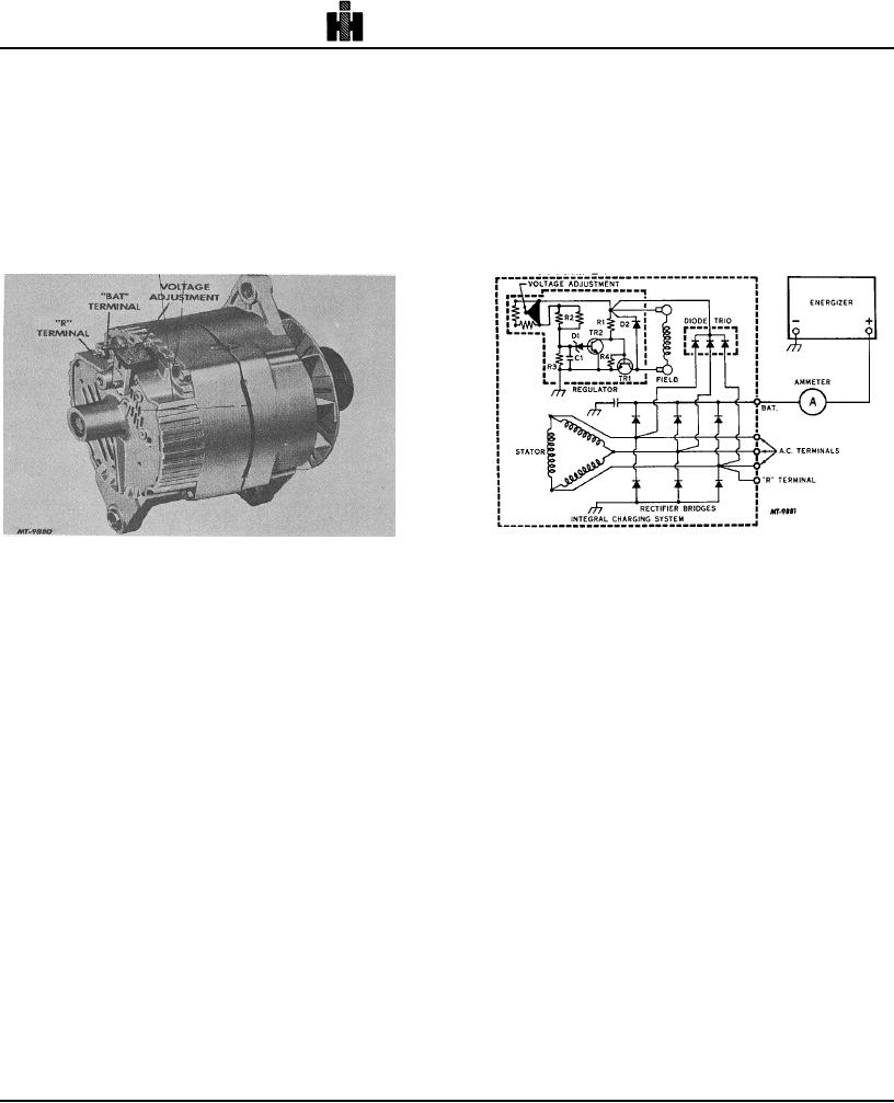
The alternator with integral charging system,
stator then supplies D. C. field current through the diode
illustrated in Fig. 1, features a solid state regulator that is
trio, the field, TR1, and then through the grounded
mounted inside the slip ring end frame. The regulator
diodes in the rectifier bridges back to the stator. Also,
voltage setting can be adjusted externally by
the diodes in the rectifier bridges change the stator A. C.
repositioning a voltage adjustment cap in the slip ring
voltages to a D. C. voltage which appears between
end frame. Only one wire is needed to connect the
ground and the "BAT" terminal. As speed increases,
integral charging system to the energizer or battery along
current is provided for charging the energizer or battery
with an adequate ground return. An "R" terminal is
and operating electrical accessories.
provided to operate auxiliary equipment in some circuits.
Fig. 1
Fig. 2
The bearings contain a supply of lubricant sufficiently
As the speed and voltage increase, the voltage
adequate to eliminate the need for periodic lubrication.
between R2 and R3 increases to the value where zener
Two brushes carry current through the two slip rings to
diode D1 conducts. Transistor TRZ then turns on and
the field coil mounted on the rotor and under normal
TR1 turns off. With TR1 off the field current and system
conditions will provide long periods of attention free
voltage decrease, and D1 then blocks current flow
service.
causing TR1 to turn back on. The field current and
system voltage increase, and this cycle then repeats
The stator windings are assembled on the inside of a
many times per second to limit the voltage to the
laminated core that forms part of the frame. A rectifier
adjusted value.
bridge connected to the stator windings contains six
diodes and electrically changes the stator A. C. voltages
Capacitor C1 smooths out the voltage across R3;
to a D. C. voltage, which appears at the output terminal.
resistor R4 prevents excessive current through TR1 at
Field current is supplied through a diode trio, which also
high temperatures; and diode D2 prevents high induced
is connected to the stator windings. A capacitor, or
voltages in the field windings when TR1 turns off.
condenser, mounted in the end frame protects the
rectifier bridge and diode trio from high voltages and
TROUBLESHOOTING PROCEDURES
suppresses radio noise.
Close adherence to the following procedures in the
OPERATION
order presented will lead to the location and correction of
charging system defects in the shortest possible time.
A typical wiring diagram is illustrated in Fig. 2. With
Only a portion of these procedures need be performed.
the integral charging system operating, A. C. voltages
It will never be necessary to perform all the procedures in
initially are generated in the stator windings by residual
order to locate the trouble.
magnetism
A basic wiring diagram showing lead connections is
shown in Fig. 3. To avoid damage to the electrical
equipment, always observe the following precautions:
252

