
TRUCK SERVICE MANUAL
ELECTRICAL
f.
If ampere output is within 10 percent of
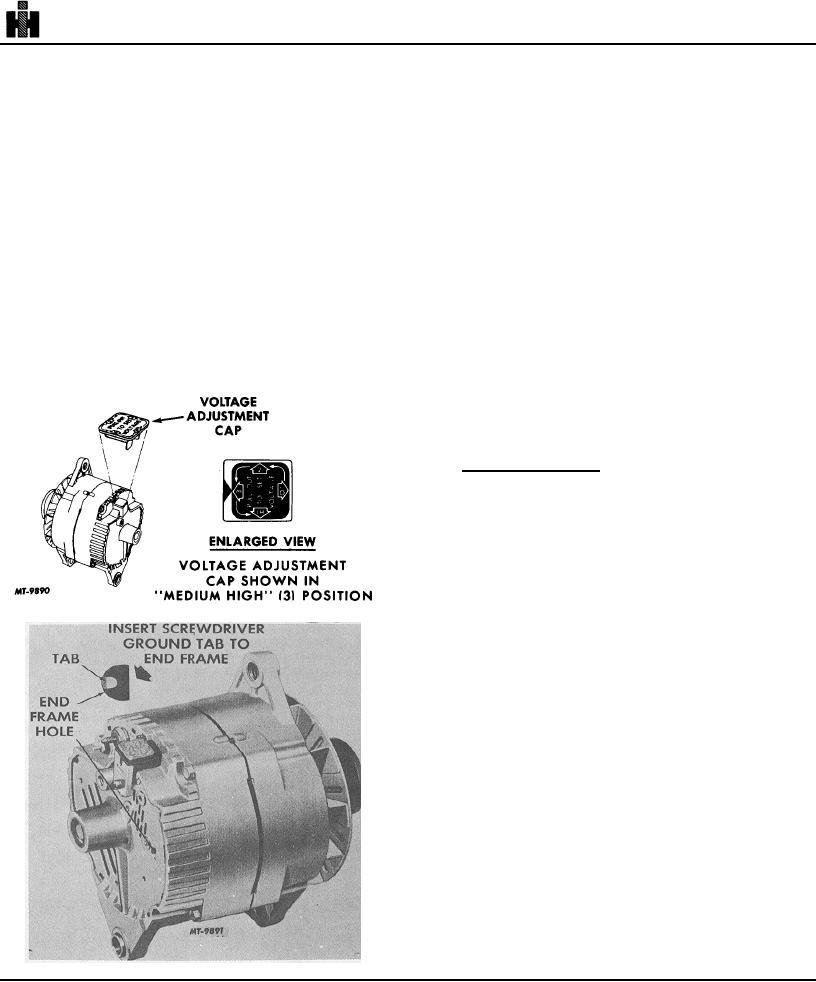
IMPORTANT: The voltage adjustment in
rated output as stamped on generator
Fig. 4 is for purposes of illustration only.
frame, integral charging system is not
The actual adjustment as shipped from the
defective. In this case, an adjustment of
factory may be in some other position
the voltage setting may correct the
depending on the application requirement.
undercharged condition. Raise the setting
g. If ampere output is not within 10 percent of
by removing the voltage adjusting cap,
rated output as stamped on integral
rotating in increments of 90 and then
charging system frame, ground the field
reinserting the cap in the connector body.
winding by inserting a screwdriver into the
As illustrated in Fig. 4, the cap is set for
test hole, Fig. 5. NOTE : Tab is within 3/4
medium high voltage. With position 2
inch of casting surface. Do not force
aligned with the arrow, the setting is
screwdriver deeper than one inch into end
medium low; position "LO" is low, and
frame.
position "HI" is the highest regulator setting.
h. Operate engine at moderate peed as
After adjusting the setting, check for an
required and adjust carbon pile as required
improved energizer condition after a service
to obtain maximum current output.
period of reasonable length, such as one
i.
If output is within 10 percent of rated output,
week.
replace regulator and check field winding.
j.
If output is not within 10 percent of rated
output, check the field winding, diode trio,
rectifier bridge and stator.
accessories off.
B. Overcharged Battery
1. Check the battery.
2. If battery is not defective or overheated, connect
a voltmeter between No. 2 terminal to ground. If
reading is zero, No. 2 lead circuit is open.
3. If battery and No. 2 lead circuit check good, but
an obvious overcharge condition exists as
evidenced by excessive battery water usage,
Fig. 4
proceed as follows:
a. Separate end frames as covered in
"DISASSEMBLY." Check field winding for
shorts. If shorted, replace rotor and
regulator.
b. Connect ohmmeter using lowest range
scale from brush lead clip to end frame as
shown in Step 1, Fig. 6; then reverse lead
connections.
c. If both readings are zero, either the brush
lead clip is grounded or regulator is
defective.
Fig. 5
254