TRUCK SERVICE MANUAL
FUEL SYSTEM
6. When the air valve is opened, air travels up the
pipe in the center of the tube type hydraulic
reservoir and exerts a downward pressure
against the column of hydraulic fluid.
7. When both the air valve and the hydraulic valve
are opened, hydraulic fluid is admitted under the
piston in the cylinder and lifts the injector into
clamped position. Any leak in the hydraulic
clamping system will directly affect injector
loading and must not be permitted.
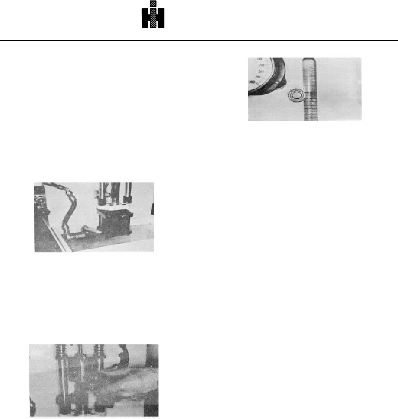
Fig. 6-1-75, F60129. Measuring fuel in vial
8. In clamped position and with the appropriate link
in place, tension on the injector is the same as it
12. Fuel is delivered to the vial during a measured
is in the operating engine. Use of the improper
number of strokes as recorded by the counter.
link will affect clamp load and upset delivery
13. A master injector which has been previously
values.
calibrated at the factory is used in setting the test
stand prior to adjusting other injectors for fuel
delivery. The master must never be tampered
with.
Note: A cylindrical injector in a pot
provides the same conditions as the
flanged injectors.
Injector Test Stand Maintenance ST-790
To obtain best service life from the ST790 Injector Test
Stand, the following maintenance practice must be
Fig. 6-1-73, F60127. Hydraulic valve
observed.
9. Fuel is delivered to the injector through the inlet
Roller Tappet And Cam Assembly
connector. Fuel pressure here is controlled at
The roller tappet and cam assembly will wear, just as any
this point by a connecting line and pressure
moving assembly and will require maintenance.
regulator. Fig. 6-1-74.
1. If tappet is worn, it should be replaced as soon
10. The second connection with the clear plastic line
as possible to prevent excessive wear on cam.
is the injector drain connection which carries
An improved tappet has been used in test
drain fuel from the injector back to the tank.
Stands built after Serial No. 0576, using a
needle bearing roller instead of the former
bronze bushed roller.
2. Do not assemble a new tappet with a scuffed
cam. If the scuffing cannot be removed with a
fine hone, the cam must also be replaced.
3. If the cam is worn into the shaft by more than
0.002 inch [.051 mm] the shaft must also be
replaced, as this condition will cause undue
loading on cam, tappet and bearings.
4. Align the cam to track 100% on the tappet roller.
5. Torque clamp type ring to 12 to 15 ft-lbs [16 to
Fig. 6-1-74, F60128. Fuel inlet connector
20 N m] or tighten setscrew in cam hub securely
11. During test stand operation, the operator starts a
and install a second setscrew on top of the
test cycle which diverts fuel to the vial so the
original one as a "jam screw"
amount of fuel being injected can be measured.
Fig. 6-1-75.
472

