
TRUCK SERVICE MANUAL
FUEL SYSTEM
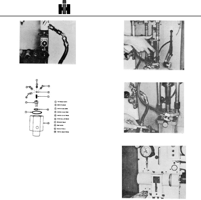
Fig. 6-1-83, F60133. Hydraulic fluid sight glass
Fig. 6-1-85, F60135. Position assembly
Fig. 6-1-86, F60136. Close hydraulic valve
Fig. 6-1-84, F60134. Injector seat restrictor orifice
11. the air valve and as the injector goes in clamped
position make sure the link is properly aligned
and engaged. Fig. 6185.
12. Check the air pressure gauge at top of hydraulic
reservoir as originally established with the load
test cell. Close the hydraulic valve to lock the
injector in clamped position. Connect the inlet
and drain connectors to the injector. Fig. 6186.
Caution:
To avoid damage to master injector, do not use ST708
Burnishing Tool when setting up test stand.
13. Start the test stand motor.
Fig. 6-1-87, F60137. Adjust to 120 psi
Note: Test oil must be a minimum of 90 deg. F [32 deg.
C] . If temperature is not up to 90 deg. F [32 deg. C]
test stand must be warmed up on a standard injector, not
Pressure (120 psi [827 kPa] ) must be maintained at all
the master injector. If temperature exceeds 95 deg. F
times during calibration and testing.
[35 deg. C], increase cold water flow. If temperature
exceeds 135 deg. F [57 deg. C] drain and replace with
new test oil.
14. Adjust the fuel pressure by turning the regulator
knob until the pressure gauge shows 120 psi
[827 kPa] . If this pressure cannot be achieved,
the trouble probably is due to a sticking air
regulator, or to a worn gear pump. Fig. 6-1-87.
475