
TRUCK SERVICE MANUAL
FUEL SYSTEM
c. Gauge line contacting frame or other member of
Clutch Adjustment
test stand thereby transmitting mechanical
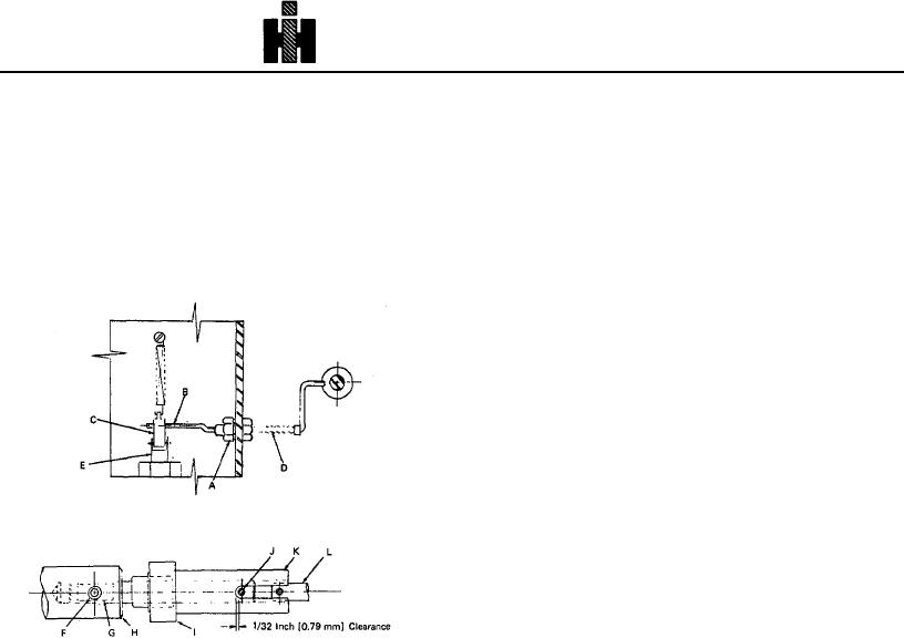
1. Manually engage clutch by fully depressing
vibration into gauge.
solenoid plunger (shown above In "Clutch Arm
Removal Procedure"). With clutch held in this
position, the cross pin (J, Fig. 6-1-77A) should
clear the driver U-slot by approximately 1/32 inch
as shown in the drawing.
2. Tighten set screw (F, Fig. 6-1-77A) against flat
provided on clutch shaft (G, Fig. 6-1-77A).
A.
Nut
E.
Plunger
I. Collar
B.
Clutch Arm
F.
Set Screw
J. Cross Pin
C.
Plunger Link
G.
Clutch Shaft
K. Driver
D.
Clutch Arm
H.
Camshaft Shaft
L. Counter Shaft
Fig, 6-1-77A, F60160. Clutch arm removal and clutch
adjustment
Gauge Damping And Mounting
One area in which increased compatibility can be
realized between factory and field test stands, is fuel
pressure gauge hand stability. Erratic action of gauge
hand is a result of'
one or both of the following factors:
1. Hydraulic pulsations being carried into the gauge
because of damping valve not being properly
adjusted. With the adjustable damping valve it
is impossible to insure that all test stands can be
adjusted to the same degree of damping.
2. Mechanical vibration being transmitted into
gauge as a result of one of the following
conditions.
a. Operation of test stand with gauge mounts
broken.
b. Gauge line positioned so it "pulls" or "pushes" on
gauge and in effect becomes a rigid member
between gauge and test stand frame.