TRUCK SERVICE MANUAL
FUEL SYSTEM
Flow Testing PT Injectors On ST-790
Flow Testing Adjustable Delivery Injectors
On ST-790
Test Stand is used to flow test the complete injector
assembly by measuring fuel delivery. The injector is
actuated under controlled conditions closely simulating
actual operating conditions. The test stand counts
injection strokes, supplying fuel at a specified pressure,
thereby measuring the delivery in a glass graduate.
1. Remove master injector ST1210, or ST1306
from test stand after calibrating test stand.
Install correct restrict orifice in cup seat, see
Table 6115, Fig. 6192, and tighten to 6 in-lbs
[Nm .
a. 0.0115 inch [.292 mm] orifice has four notches.
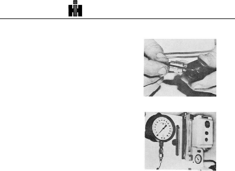
Fig. 6-1-92, F60142. Installing restrictor orifice
b. 0.013 inch [.33mm] orifice has two notches.
c. 0.020 Inch [.51 mm] orifice has six notches.
d. 0.026 inch [.66 mm] orifice has one notch.
Note: Delivery for injectors listed in Table 6115 under
heading "Approx. Strokes" as 20% is established by
setting ST790 Stand with ST1210, Master Injector; then
turning back the counter by 20%. For example, if test
stand counter was read at 1050 with master, the
injectors to be tested would be run at 840 counter
strokes.
Comparing Injector Flow With ST1129
A new flowmeter, ST1129, is available to provide a quick
comparative indication of injector flow on the ST790 Test
Stand without running through a complete test cycle.
However, this flowmeter is in no way meant to replace
Fig. 6-1-93, F60221. Front view of ST790 with ST1129
the present method of measuring injector delivery. Fig.
installed
6193.
Operating Instructions
PT (type D) Injectors
1. the first injector of the set to be flowed into the
ST790 Test Stand is used to flow test the complete
ST790 stand per normal procedure and
injector assembly by measuring fuel delivery. The
complete calibration.
injector is actuated. under controlled conditions closely
2. Before removing injector from ST790, note
simulating actual operating conditions. The test stand
flowmeter value.
counts injection strokes, supplying fuel at a specified
3. Install second injector and start test stand, do
pressure, thereby measuring the delivery in a glass
not hit flow start button, observe flow value.
graduate.
Compare with previous injector and burnish
1. Remove master injector from test stand after
orifice until reading is slightly below first injector.
calibrating test stand. Install restrictor orifice In
4. Complete calibration of injector. A little practice
cup seat, see Table 6115, Fig. 6192 and tighten
with the flowmeter will save considerable time In
to 6 inchpounds [.7 Nm]. pounds [.069 kg mi .
"burnishing in" injectors to reach the correct flow value.
a. 0.020 inch [.51 mm] orifice has six notches.
b. 0.026 Inch [.66 mm] orifice has one notch.
477

