TRUCK SERVICE MANUAL
FUEL SYSTEM
Note: Delivery for injector with approximate strokes of
800 in Table 6115 is established by setting ST790 Stand
with master injector, then turning back the counter by
20%. For example, if test stand counter was read at
1050 with master, the injectors to be tested would be run
at 840 counter strokes.
2. Lubricate inside of Service Tool 3375086,
ST1058 or Body with test oil so Injector "0" rings
will slide into adapter without damage to "0"
rings.
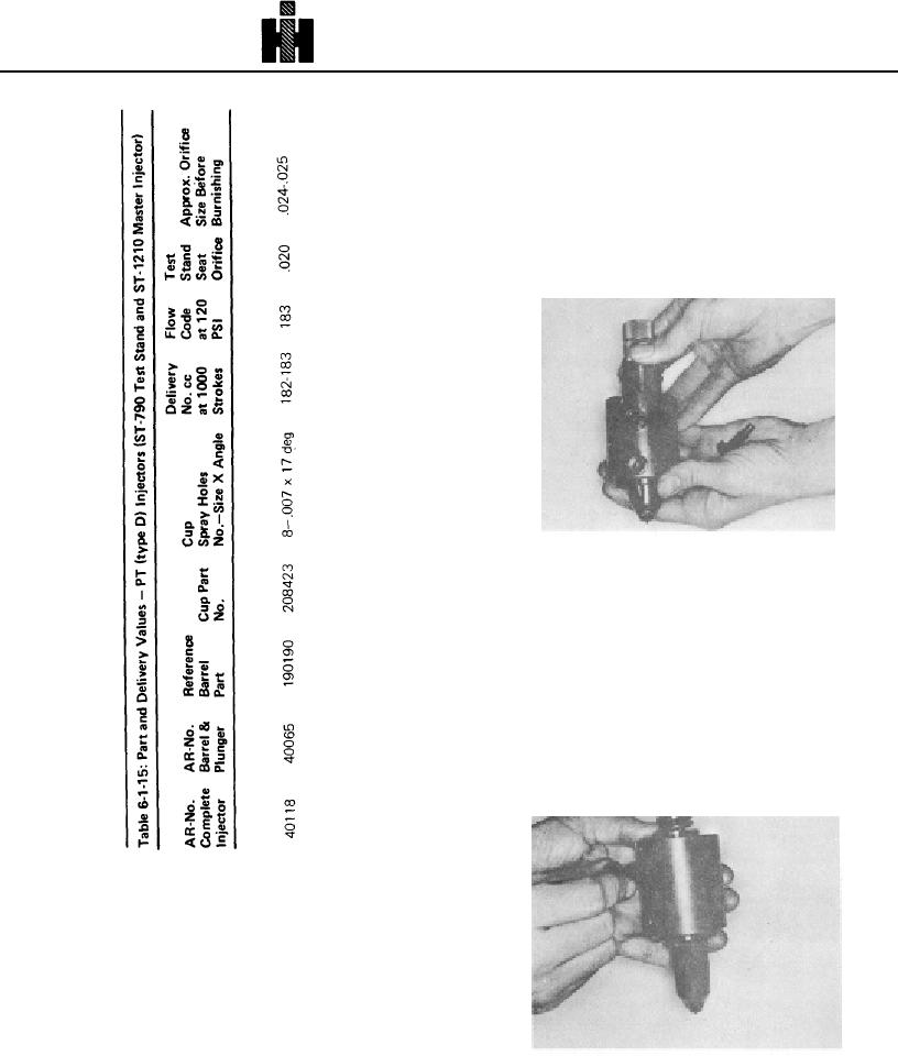
Fig. 6-1-109, F60203. Center injector inlet in ST1058
inlet hole
3. Seat injector in body so injector Inlet aligns with
body inlet hole. Fig. 61109. Tighten locating
screw. Fig. 61110.
4. Remove spring and plunger from injector
adapter. Leave spring off and install plunger into
adapter.
5. Perform ball valve seating check before
calibrating injector.
a. Attach test stand inlet pressure line to drain
connection of Service Tool 3375086, ST1058
Body.
Fig. 6-1-110, F60212. Tighten ST1058 locating screw
478

