
TRUCK SERVICE MANUAL
FUEL SYSTEM
Check 1 - Drain Flow Lines
Correction
Replace per line K in Fig. 6-1-121.
Cause
Use of a line with less than 5/16 inch [7.95 mm] I.D. or
crimp caused by sharp bend in drain line.
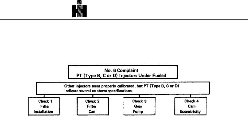
Check 1 - Filter Installation
Correction
Install filter.
Cause
Filter assembly must be in specified location as shown.
Removal of the filter assembly from the circuit.
Correction
Installation of the filter assembly in the suction side of the
gear pump.
Filter must be of specified type.
Check 2 - Filter Can
Correction
Cause
With the pressure regulator by-pass line (line G, in Fig.
6-1-121) completely blocked, check the gear pump
Installation of a smaller or more rigid than standard filter
against a 0.045 inch [11.1 43 mm] orifice installed in line
can.
L.
The gear pump is acceptable if it delivers 80 to 120 psi
Check 3 - Gear Pump
[552 to 827 kPal during this check.
If the gear pump delivers less than 80 psi [552 kPa],
Cause
check the fuel strainer for clogging end consequent
pump suction restriction and clean if necessary; the gear
Low gear pump delivery.
pump must be replaced.
Check 4 - Cam Eccentricity
Correction
Cause
Check as follows:
Cam base circle eccentricity.
(a) Align timing wheel mark and pointer.
(b) Install ST-790-5111 load cell with regulated air
pressure to give 380 lbs. [172 kg] load. Repeat the
clamping several times to assure that the setting of the
clamping load is correct.
491