TRUCK SERVICE MANUAL
Aneroid
Aneroid Adjustments
Aneroids must not be removed, disconnected or otherwise
rendered ineffective on these engines, nor should settings be
altered to exceed those specified for the aneroid as shown In
Table 521.
Description
1. During acceleration or rapid engine load changes,
turbocharger speed (intake manifold pressure) change
inherently lags behind the power or fuel demand exercised by
opening of the throttle.
2. This lag does not exist in fuel system. therefore, an
over rich or high fuel to air ratio, usually accompanied by
heavy smoke, , occurs until the turbocharger "catches up "
3. The function of the aneroid is to create a lag In fuel
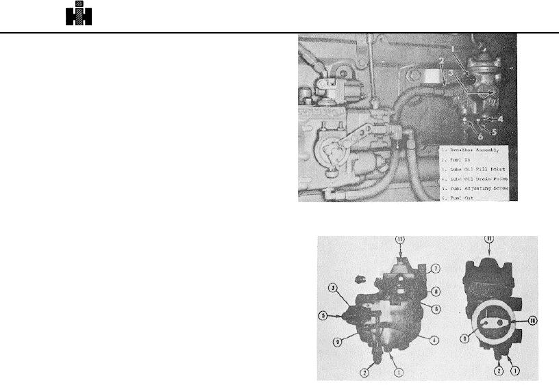
Fig 52 1, N 11026 Aneroid mounted on engine
system so response is equivalent to that of turbocharger, thus
controlling engine smoke level.
Fuel Flow
1. Fuel from outlet side of fuel pump enters aneroid and
goes through starting check valve area (5, Fig. 522). Aneroid
AR40600 series does not have a starting check valve but must
have a fuel check valve in supply line.
2. The starting check valve (3) prevents aneroid from
bypassing fuel at engine cranking speeds. For speeds above
cranking, fuel pressure forces the check valve open,
allowing fuel to flow to valve port (4) of shaft (9)
3. Shaft (9) and Its bore form the bypass valve This
Fig 522, F5244 Aneroid cutaway
shaft and bore allow passage or restriction of fuel flow in a
similar manner as throttle shaft and sleeve In PT fuel pump
9. The aneroid does not by-pass fuel under full throttle
lug down conditions until speed is low enough to reduce intake
4. allowed to pass through bypass valve is returned (2)
manifold air pressure to aneroid operating range (usually
to suction side (inlet fitting) of PT gear pump The
below engine stall-out speed.)
bypassed fuel reduces fuel pump output to engine and
reduces fuel manifold pressure In proportion to the bypass
Installing Aneroids On Fuel Pump Test Stands
rate. Fig. 521.
Precision setting
and/or checking of Aneroids is
5. The shaft and sleeve are bypassing fuel when arm
accomplished by simulating engine operation on a fuel pump
(10) of lever is resting against adjusting screw (1). The
test stand. Cummins ST848 Fuel Pump Test Stand must be
amount of fuel bypassed is adjusted by this screw, which
equipped as follows
protrudes from bottom of aneroid.
1. Fabricate a suitable bracket or mount the aneroid on
6. The lever arm connected to piston (8) by actuating
fuel pump test stand. This .bracket may be used to mount an
shaft (6)., rotates shaft, closing valve port. The lever is rotated
air regulator, such as used on ST790 or ST990 Injector Test
by action of air Intake manifold pressure (11) against piston
Stands, and a mercury manometer of suitable scale length or
and diaphragm (7), moving actuating shaft downward
30 inch pressure gauge of known accuracy.
against resisting spring force. Fig. 522.
2. Air pressure from regulator must be piped to top of
7. Anytime engine Intake manifold air pressure is above
aneroid to actuate bellows.
preset bellows "air actuation pressure," aneroid is "out of
system.
3. Tee off regulator air line (outlet) Into manometer or
8. The aneroid begins dumping when Intake manifold air
pressure gauge. Service Tool is ST1256.
pressure drops below preset value as happens after
deceleration In traffic, deceleration during gear shifts, down
grade motoring with closed throttle or down grade operation on
light load portion of governor droop curve.
540

