
TRUCK SERVICE MANUAL
pressure decrease is noted. Compare air pressure to that
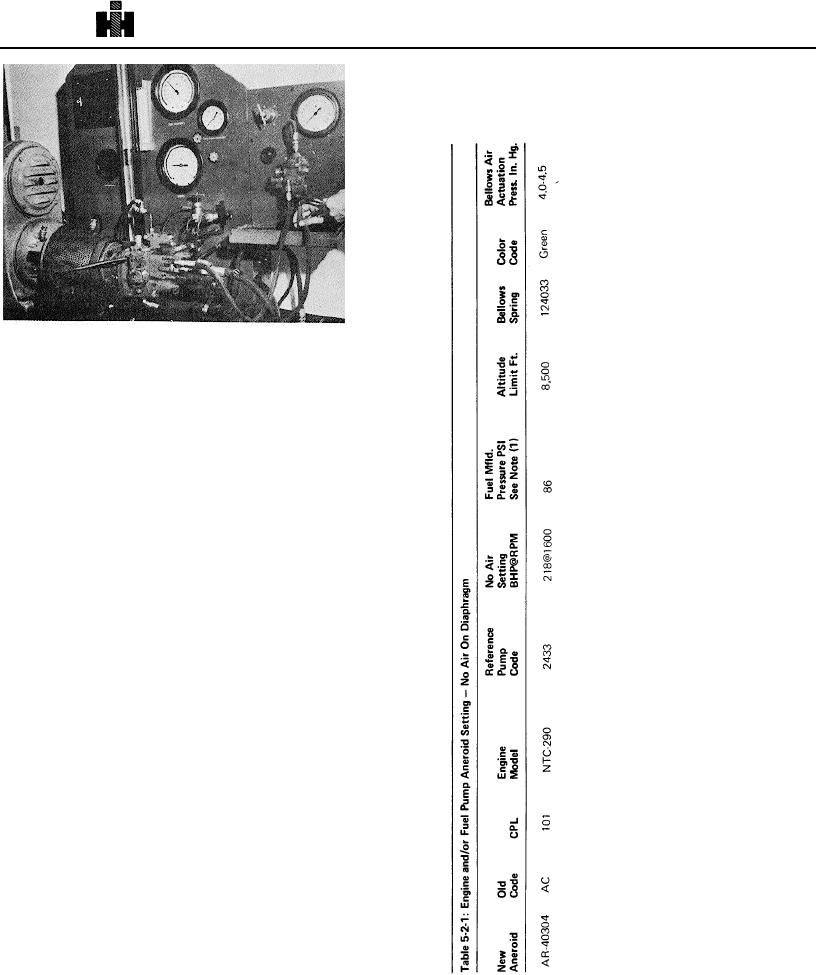
shown in Table 5-2-1. This check must always be made with
decreasing pressure only. Internal friction in aneroid bellows,
spring and linkage causes air pressure requirements
Fig. 5-2-3, F5287. Adjusting aneroid fuel screw
Testing Aneroid
Adjusting Fuel Screw
1. Mount a fuel pump on. fuel pump test stand which
has been calibrated to the same code as that on, or will be
used, on engine. For instance, if aneroid is intended for use
on an engine equipped with fuel pump calibrated to code
No.2049, use a pump set at same code (2049) to set aneroid.
2. Plumb aneroid to fuel pump in the normal manner.
Fig. 525
3. Start fuel pump test stand and purge all air from
system.
4. Adjust air regulator to appl y 30 inch [76.2 cm] Hg.
pressure on aneroid bellows.
5. Set fuel pump at rated speed calibration point
(Manifold PSI @ RPM and Flow Reading) specified for pump
code.
CAUTION
The flow control valve setting must not be altered during
the following checks.
Altering flow will give false
adjustments,
6. Reduce test stand speed to that shown in Table 5-2-1
under BHP @ Speed.
7. Set air regulator to "O" inches of mercury. Adjust
screw in bottom of aneroid housing to value specified under
"Fuel Manifold Pressure" for pump and aneroid code shown in
Table 5-2-1. Fig. 5-2-3.
Note: See section entitled, "Engine Altitude Derate and
Aneroid Settings" If engine requires a fuel pressure setting
lower than specified in Table 5-2-1 because of altitude.
8. Return air pressure to 30 inches [76.2 cm] Hg.
Decrease air pressure slowly while observing fuel pressure
gauge. When aneroid by-pass has just opened, a fuel
541