
TRUCK SERVICE MANUAL
PROPELLER SHAFT
General
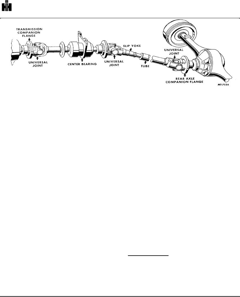
Fig. 1 Typical Propeller Shaft Installation
GENERAL
ameter, length and operating speed are all carefully
considered during the development of propeller shafts.
One of the major problems encountered in the early
All propeller shaft assemblies have a critical speed
production of motor vehicles was the transmission of
because of the aforementioned factors; therefore, it can
power from the engine through a gear box to the driving
be readily accepted that propeller shafts are designed for
wheels.
specific applications. Disregard for correct application
could result in propeller shaft failure with extremely
It was soon learned that because of the various
violent and hazardous consequences. Shaft
angles involved in mounting the engine, gear box and
replacement must always be of the same design and
driving wheels, it would be necessary to develop a
material specification as the original equipment shaft to
means of transmitting a smooth flow of power regardless
assure satisfactory service.
of the angles encountered through spring deflection and
frame flexing during vehicle operation.
DRIVE LINE COMPONENTS
The chain drive was used to solve these problems;
There are several important units which make up the
however, it brought about problems of other natures-
propeller shaft or drive line, as it is often times referred
such as short service life caused by the inability to keep
to, Fig. 1. The shafts themselves are of tubular
an exposed chain clean and adequately lubricated.
construction and have splined slip yokes which provide
for shaft elongation. Universal joints, though they may
The search for an improved method of power
vary as to manufacture, are of the same general design,
transmission continued and eventually brought about the
and all have steel roller bearings. Companion flanges
use of the propeller or drive shaft with universal joints.
are of both the yoke type and disc type. The center
With the propeller shaft all bearing surfaces are
bearing, provided on some models, is also a part of the
protected by dustproof housings and seals and can be
drive line and helps to support the propeller shaft,
properly lubricated, thus greatly extending the service life
providing a smooth delivery of power to the driving
of its components. This eliminated the problems
wheels. When all of the above units have been properly
involved with the use of the chain drive.
installed, satisfactory operation is assured. When
something happens which may adversely affect any of
The propeller shaft as we know it today is
them, drive line vibration may result. Vehicle speeds
constructed of tubing rolled from flat steel and butt or
above those recommended may also cause vibration.
seam welded. This insures a more uniform wall
thickness, providing better balance than can be obtained
Companion Flanges: The companion flange mounting
nuts and the bolts that attach the propeller shaft to the
from drawn tubing.
flange must be tight to assure drive line balance. The
least degree of looseness in the flange mounting nuts or
Propeller shafts of today's vehicles occasionally
the shaft attaching bolts is enough to cause excessive
rotate at very high speeds and are sometimes quite long.
(out-of-balance) vibration at high propeller
These two factors have a tendency to induce shaft
whirling, that is, flexing of the shaft from a true center
line. To minimize this tendency, tubing wall thickness, di
591