
PROPELLER SHAFT
TRUCK SERVICE MANUAL
General
possible. See Fig. 8. Road test the vehicle or spin the
propeller shaft at the locating mark. Hold the weld
drive line; then, by moving the weight to various locations
material to a minimum.
on the shaft, find the point of least vibration. Increase or
decrease the weight at this point to obtain as perfect a
CAUTION: When using hose clamps to attach loose
balance as possible. Mark the location of the weight on
weights to a propeller shaft (when checking for
the shaft and remove the hose clamp and weight. Weigh
vibration), make sure that the weights are clamped
the weight and add 3/8 of an ounce for the clamp screw
securely to the shaft t avoid the hazard of weights
and nut. Select a piece of steel of this total weight and
flying off.
tack weld to the propeller shaft at the locating mark.
Hold the weld material to a minimum.
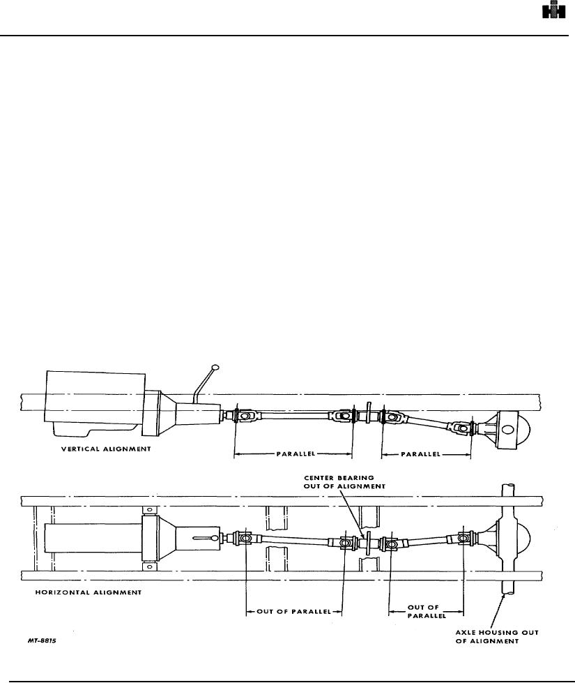
COMPANION FLANGE ALIGNMENT AND RUN-OUT
For vehicles with a single propeller shaft use an
An important consideration for maintaining
adjustable hose clamp and a small weight
acceptable propeller shaft alignment is to keep all
(approximately 1/2 ounce). Clamp the weight to the front
propeller shaft companion flanges or yokes parallel, Fig.
end of the shaft and cut off the excess material of the
2. In other words, all flanges or yokes must be
band as close to the clamp as possible. Road test the
perpendicular in both vertical and horizontal planes to the
vehicle or spin the drive line; then, by moving the weight
engine crankshaft, Fig. 9. It should be noted, however,
to various locations on the shaft, find the point of least
that the flanges of a "broken back" type drive line are not
vibration. Increase or decrease the weight at this point to
parallel in the vertical plane, Fig. 3.
obtain as perfect a balance as possible. Mark the
location of the weight on the shaft and remove the hose
These flange angles will be discussed later. For the
clamp and weight. Weigh the weight and add 3/8 of an
moment we will consider the parallel joint type drive line.
ounce for the clamp screw and nut. Select a piece of
steel of this total weight and tack weld to the
Fig. 9. Drive Line Horizontal and Vertical Alignment
596