
TRUCK SERVICE MANUAL
PROPELLER SHAFT
General
Auxiliary Transmission Flange Vertical
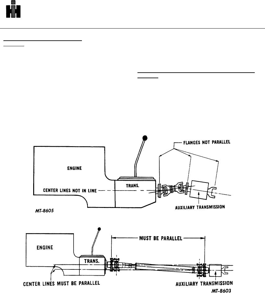
main transmission output shaft universal joint and the
Alignment
auxiliary transmission input shaft universal joint to
operate at different working angles, which is not
As previously mentioned, the angularity of the
permissible. The center lines of the engine main and
complete drive line must match the main transmission
auxiliary transmissions must be parallel, Fig. 14.
companion flange; therefore, all remaining flanges must
be checked to determine run-out and vertical alignment.
Rear Axle Pinion Shaft Companion Flange Vertical
Alignment
Procedures required are the same as for checking run-
out and vertical alignment of main transmission
The center line of the rear axle pinion shaft
companion flange.
should be parallel with the engine crankshaft, Fig. 16.
However, manufacturing may elect to position the pinion
If the auxiliary transmission companion flange is not
shaft center line of the rear axle at any given angle. For
properly aligned vertically, check for loose or worn
instance, the propeller shaft and universal joints can form
transmission mountings, as this will position the auxiliary
what is known as a "broken back" drive line between the
transmission mainshaft on a horizontal plane that is not
transmission and rear axle.
parallel with the main transmission mainshaft and engine
crankshaft, Fig. 14. This causes the
Fig. 14. Main and Auxiliary Transmission Center Lines Not Parallel
Fig. 15. Engine, Main and Auxiliary Transmission Center Lines Parallel
599