TRUCK SERVICE MANUAL
PROPELLER SHAFT
General
Rear Axle Pinion Shaft Companion Flange
magnetic base protractor on the machined flat of the
Horizontal Alignment
upper or lower bearing retainer transversely with the
To check the horizontal alignment of the rear axle
propeller shaft. Turn yoke until protractor dial reads zero
pinion shaft companion flange, use lame procedure as
degrees. Without moving the yoke, place protractor on
for checking main or auxiliary transmission flange.
the opposite bearing retainer. If protractor readings differ
An alternate method for checking pinion flange
more than 1/2 degree, the yoke is probably distorted and
horizontal alignment is by measuring the distance from
should be replaced.
the ends of a straight edge placed across the frame to
If bearing retainer has been removed, place
the centers of the rear axle (distance "Y", Fig. 17).
protractor on machined flat of yoke. If cap is an integral
These measurements may not vary more than 1/8".
part of bearing retainer, protractor may be placed on cap,
providing cap is flat. If cap is dome shaped at all,
Horizontal misalignment of the pinion flange can be
remove cap and retainer and place protractor on
corrected by eliminating one or all of the possible
machined flat of yoke.
causes, which are:
All drive line yokes can be checked for distortion
1. Loose or sheared spring seat dowels.
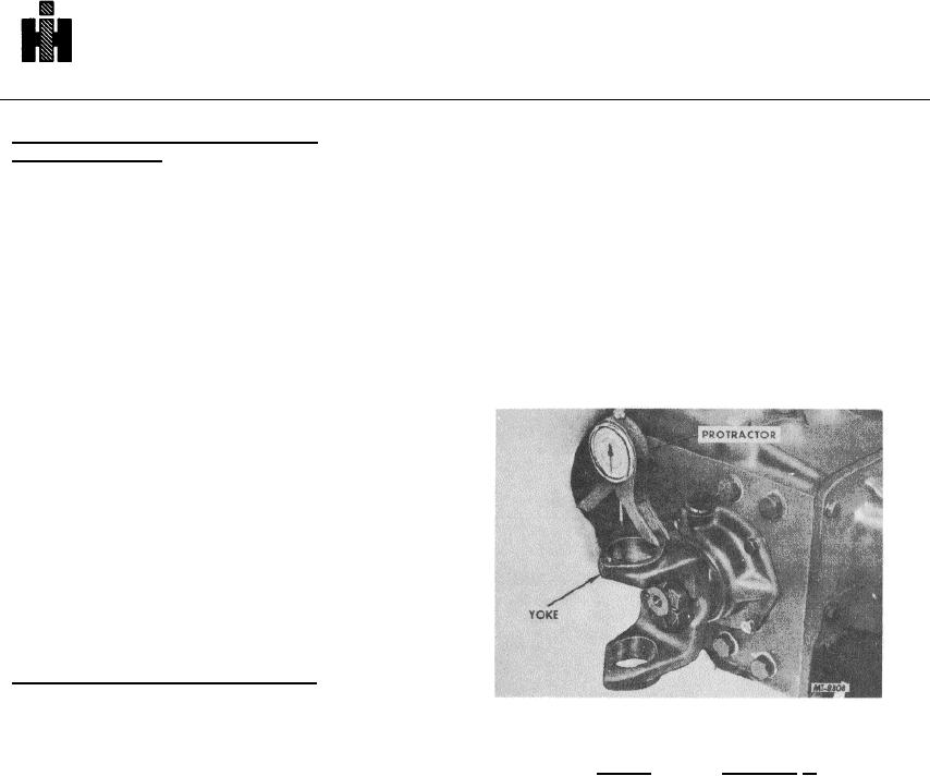
using either the bar stock or protractor, Fig. 18.
2. Loose spring clips.
3. Loose spring shackle brackets.
The rear axle pinion flange alignment can be
checked by the same method as the forward rear axle.
YOKE ALIGNMENT AND DISTORTION
Correct alignment of universal yokes is as important
as proper flange alignment. Before checking their angle,
it is necessary to inspect the yoke for lug distortion or
damage. The same standards of alignment, distortion
and runout apply to yokes. As with a flange, a yoke can
often be revolved on its splined shaft to improve
concentricity.
Checking Yoke for Distortion and Run-Out
Fig. 18 Checking Yokes for Distortion
A straight piece of round bar stock which is a slip fit
in the two universal joint bearing bores can be used as a
To check yoke run-out, disconnect the propeller
gauge bar. If the gauge bar is a slip fit through both
shaft. Insert a straight piece of selectively fit round bar
bearing bores simultaneously, the bores are properly
stock through the yoke bores so that it extends equally
aligned, and the yoke is not distorted or damaged. If the
on each side of the yoke lugs. Securely mount a dial
bar goes through one bearing bore but strikes the inner
indicator so that the indicator stylus can be placed
face of the opposite lug, the yoke is distorted and should
against the bar stock adjacent to the yoke lug. Set
be replaced.
indicator to zero when stylus is on high point of bar stock.
If a gauge bar of correct diameter is not available,
Rotate yoke 180 degrees and again position stylus on
yoke distortion can be checked using a protractor. Some
high point of bar stock. Dial indicator reading should be
types of universal joints use a bearing cap separate from
zero. Permissible runout should not exceed .005".
the trunnion bearing retainer, while others have the cap
If bar stock is not available, an alternate method
as an integral part of the bearing retainer.
is to position dial indicator stylus against the machined
When checking a yoke having a separate cap and
outside diameter of the bearing retainer, Fig. 19.
bearing retainer, remove the lock strap and cap. Allow
the trunnion bearing retainer to protrude approximately
NOTE: Expose bearing retainer only enough to accept
1/8" beyond the yoke lug. Rotate the yoke until the "C"
dial indicator stylus, otherwise, retainer may cock in yoke
formed by the yoke is in a vertical position. Place an SE-
bore and cause an erroneous indicator reading.
2067
601

